Osburn AC01340 User Manual
Page 16
16
5
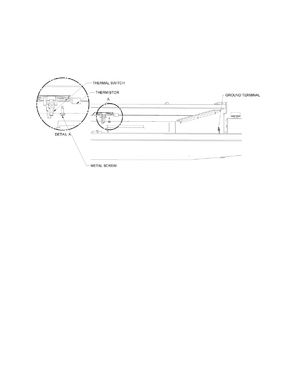
Finally, the ground terminal is to be secured to the fireplace frame and the thermistor to
the fireplace using the same metal screw already securing the thermal switch (see
Figure 8).
Figure 8
6
Connect a white wire to the ACCOM terminal of the PC board. Connect a black wire to
the ACHOT terminal of the PC board. Connect a green or nude wire from the FRAME
terminal of the PC board to the frame of the fireplace. Run an 18/3 (18 AWG) cable from
the PC board to the heat distribution blower terminal. Connect the white lead on
FANCOM in the PC board and on N at the heat distribution blower terminal. Connect
the black lead on FANHOT in the PC board and on L at the heat distribution blower
terminal. Connect the green or nude lead on FANFR in the PC board and on GROUND
at the heat distribution blower terminal (see Figure 9).
In the event that an optional thermostat (AC05558) is used, simply connect the 2 leads
coming from the thermostat to the TSTAT on the PC board (see Figure 9).
Even though it is not supplied, it is strongly recommended to install a switch on the
black lead to allow turning OFF the heat distribution blower manually before you open
the fireplace doors. If the blower is running, the smoke could be drawn out of the
fireplace instead of up the chimney and sparks may be drawn into the insulated
flexible pipe of the forced air kit. Note that this switch will not turn the heat distribution
blower ON unless the fireplace is hot enough (See Figure 10).