Edgelit, For type: internal power supply for use with, Type exit signs – Radionic ZXE–5000-UNVSeries User Manual
Page 6: Page i -2
KIT CONTENTS & INSTALLATION INSTRUCTIONS for Part Number: ZXE-5000-I-UNV
for type: INTERNAL POWER SUPPLY for use with
EDGELIT
type exit signs
•
One (1) LED Strip with power supply mounted inside the aluminum extrusion. (note: power supply not user serviceable and
may not be replaced)
•
Two (2) Mounting Brackets for ZXE-5000-I-UNV LED Strip
•
Two (2) each: Screws, Washers, Nuts
•
Three (3) Wire Connectors
I
NSTALLATION
I
NFORMATION
:
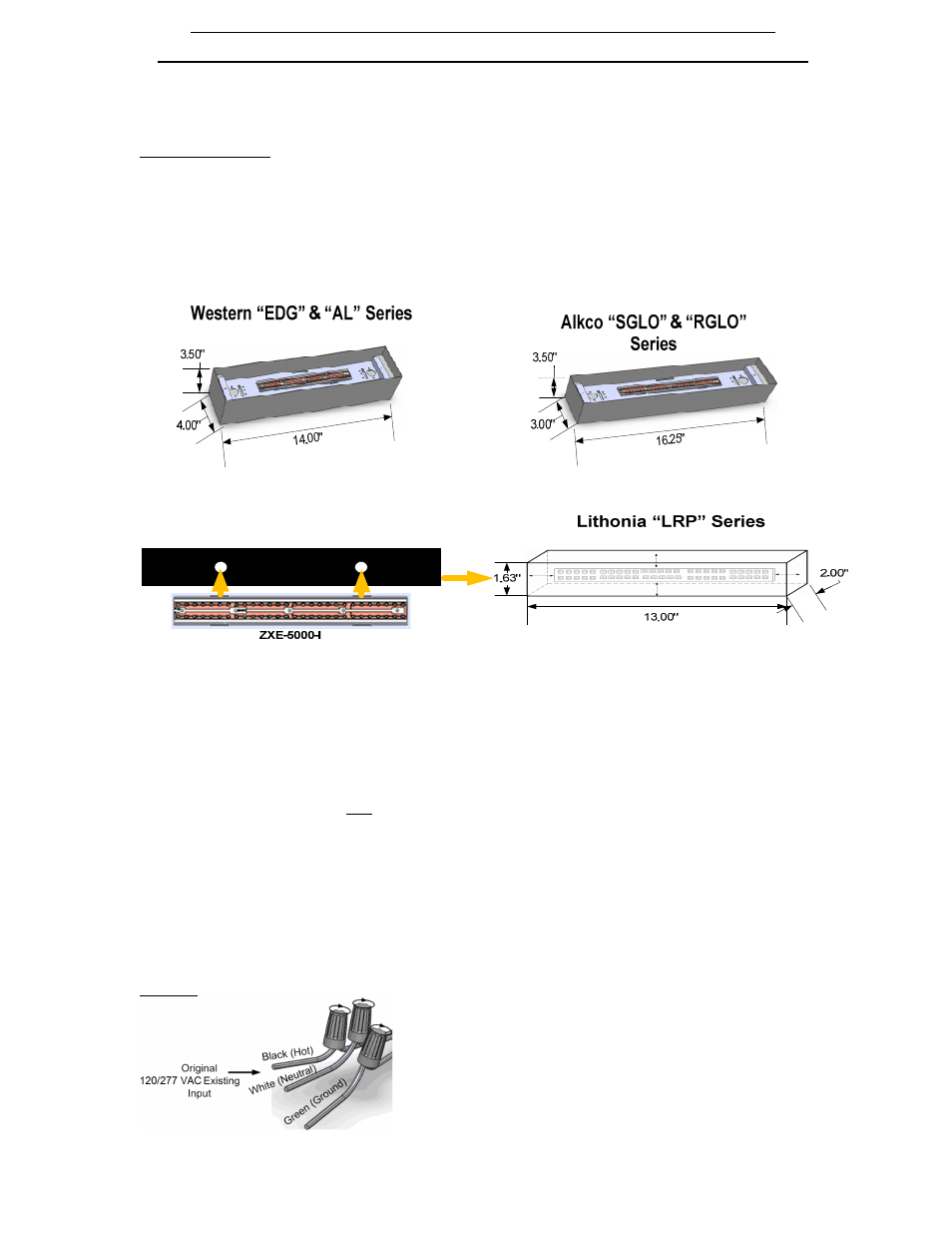
1. Select a suitable mounting location in the exit sign fixture. See FIGURE D1 (below) The LEDs should be pointed down towards the
word “EXIT.” If you notice that the words on the sign are not lit up to full brightness and visible from at least 100 ft, remove the LED
fixture and start over. Never mount the LED strip on the right/left side of the fixture. The power supply may be mounted on the
right/left side along the long portion of the sign box. Be sure not to block any vents.
FIGURE D1:
If retrofitting an Edge-lit type of exit sign, use the diagram below that corresponds to your exit sign brand/model:
(note LED strip is mounted in CENTER of mounting area) ‘
2. To install the ZXE-5000-I, use the two mounting brackets, washers, nuts and two screws (provided). Pre-drill holes for mounting
brackets and corresponding hardware in a suitable location. The LED strip must be centered in the mounting area of fixture. Place
screw through center hole of bracket. Using a Philips screwdriver and install the mounting brackets to the suitable mounting location
on the fixture (as described in step #1 and figure D1) using the screws, washers and nuts (provided). Screw in the mounting brackets
first to the suitable mounting location on the fixture (as described in step #1 above), then snap in fixture. (See diagram below, left). *
For Lithonia LRP Series: follow above instructions, but mount to the Formex provided instead of metal hardware. Slide in the plastic
after mounting is complete.
3. Snap in the wire (provided) by inserting the end with plastic clip into the fixture in the holes marked “in.”
4. To remove a fixture and power supply after installation, use a small screwdriver to slightly pry one side of the metal mounting
brackets open and then twist the fixture away from that side of the bracket.
6. WIRING THE FIXTURE
Turn the main breaker/fuse to the fixture off
Refer to FIGURE D2 (next page, I-2)
Bring the power input leads (black/white/green or hot/neutral/ground) to the input leads of the light fixture as shown.
Twist one lead of the stripped Input Lead to the Black (Hot) power input lead. Secure with wire connector (provided).
Twist second lead of the stripped Input lead to the White (Neutral) power input lead. Secure with wire connector (provided).
Twist green grounding wire attached to LED fixture to the Green (Ground) power input lead. Secure with wire connector
(provided).
After proper connections are made, in accordance with the National Electrical Code and local codes, turn on the main power
FIGURE D2:
PAGE I-2