REMKO ATR-3 User Manual
Page 11
11
G
Note: When the indicators in the lower area of the weekly clock
timer display are blinking, this indicates that the ceiling fans have
been separated from the control unit as a result of a defect.
G
Caution: The unit can be damaged if it is connected improperly!
We are not liable for damages that are the result of incorrect con-
nection and/or improper use!
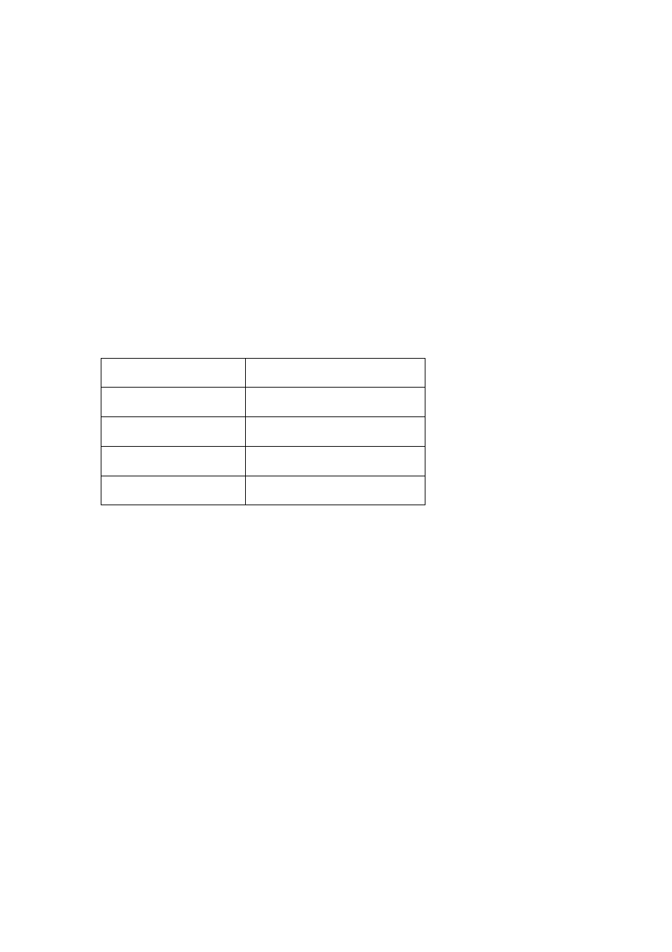
Max. line length
Line cross-section (Cu)
30 m
0.50 mm²
45 m
0.75 mm²
60 m
1.00 mm²
90 m
1.50 mm²
•
When installing the unit, make sure that the electrical lines, for exam-
ple, power supply and relay connection lines, cannot come into con-
tact with low-current supply lines, such as sensor lines (minimum dis-
tance 4 mm for basic isolated line conductors).
•
Make sure that there is adequate protection to prevent connection
conductors from becoming loose that meets the requirements of EN
60730 Part 1. This can be achieved, for example, by securing the lines
with cable bindings.
•
Compliance with VDE 0100, EN 60730, Part 1, as well as all regula-
tions of the local EVU must be assured.
•
Use the sensor lines in accordance with the requirements. Observe
the maximum line length and required minimum cross-sections!
G
Note: If the unit does not function as expected, first check the
power supply and that the unit has been properly connected.
Operation/handling which does not comply with these
instructions is prohibited! In cases of non-compliance, we
assume no liability and the guarantee becomes null and void.
For the guarantee to be valid, the purchaser or his customer must
completely fill out the
"guarantee certificate"
enclosed with all
units and send it back to REMKO GmbH & Co. KG.