4 azimuth and elevation slow speed codes, 5 azimuth and elevation angle display – Research Concepts RC2000C User Manual
Page 61
RC2000C Az/El Tracking Antenna Controller
Chapter 5
Modes Function Description
53
Research Concepts, Inc. • 5420 Martindale Road • Shawnee, Kansas • 66218-9680 • USA
www.researchconcepts.com
3, 6, 12, 24, 48, 96 ENT,BKSP,SCRLL ^v
5.10.4 Azimuth and Elevation Slow Speed Codes
The Azimuth and Elevation Slow Speed CONFIG items can be used to set the azimuth and elevation
slow speed codes. Please refer to section 3.5 for more information on the slow speed system. The
range of values for these parameters is from 1 to 254. Higher numbers give faster speeds. (For a
given axis, a slow speed code of 254 will disable the slow speed system for that axis - all movement will
occur at fast speed.) For most motor/sensor combinations, a slow speed code in the range of 140 to
175 is appropriate. If the slow speed codes are changed, test the slow speed system to insure that the
selected values yield reasonable results. Access to these CONFIG mode items are allowed only when
the Expert Access flag is set. The procedure used to determine the slow speed parameters is
described in section 3.5.
To implement slow speed the RC2000 pulse width modulates the voltage applied to the drive motors.
In some applications, the +/- 36 volt output of the RC2000 is used to activate controls that energize the
motors which actually move the antenna. For these applications slow speed should be disabled by
setting the azimuth and elevation slow speed codes to 254. More information on these applications is
available in the paper entitled ‘Controlling Antennas Powered by AC or Large DC Motors with the
RC1000 or RC2000 Antenna Controllers’. With some controller’s this paper is included as an
addendum to this manual. The paper is also available from RCI.
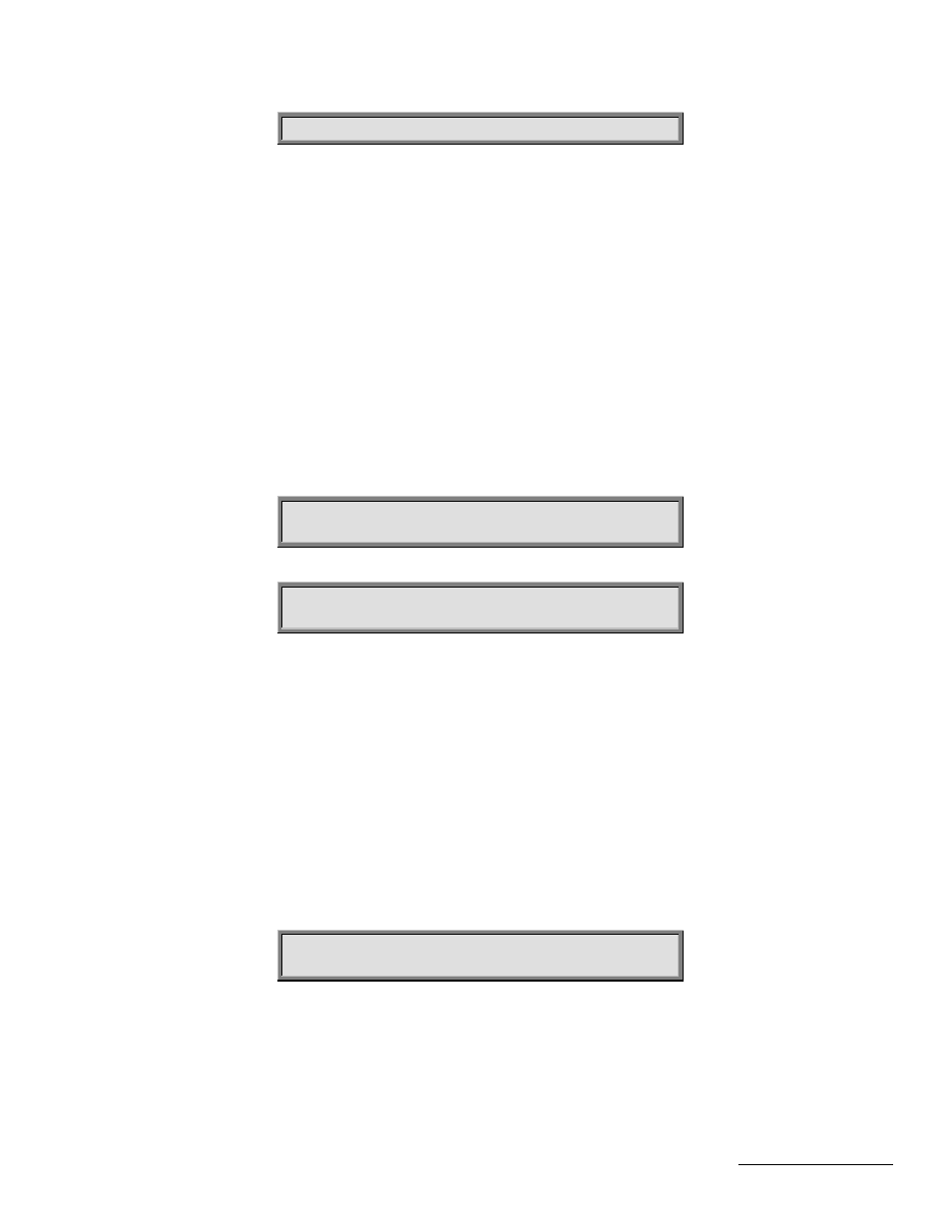
AZIM SLOW SPEED 0-254:253 CONFIG
ENT,BKSP,SCRLL ^v
ELEV SLOW SPEED 0-254:253 CONFIG
ENT,BKSP,SCRLL ^v
5.10.5 Azimuth and Elevation Angle Display
The RC2000C has the ability to display azimuth and elevation position in an angle format. This feature
can greatly facilitate the process of locating satellites for systems that use an elevation over azimuth
type antenna mount. Please see section 3.7 for more information on how to enable and calibrate this
feature. Access to these CONFIG mode items is allowed only when the Expert Access flag is set.
Briefly, to calibrate the angle display feature, the user locates two satellites and records their azimuth
and elevation position count values. The scale3.exe PC program (for IBM compatibles - shipped with
each controller in the back of this manual) is then used to calculate azimuth and elevation scale factors
that are entered into controller via the CONFIG mode items described in this section. The scale3.exe
program prompts for the antenna latitude and longitude, and the longitude, azimuth position count, and
elevation position count values for a pair of satellites which have been located with the controller.
The Angle Display Enable item is the controlling item for the other items described in this section.
When this parameter is set to 1 (enabled), azimuth and elevation positions are displayed in an angle
format using the other items described in this section.
ANGLE DISPLAY ENABLE:0 CONFIG
0-DISABLE, 1-ENABLE ENT,BKSP,SCRLL ^v
The Display Az Gain and Display Az Offset items are used to calibrate the display of azimuth position
according to the following formula:
(Northern Hemisphere)
Display_Angle (tenths of degrees) = 1800 + ((100 * (Azim_Position_Cnt - Display_Az_Offset)) /
Display_Az_Gain)