RF Neulink NL900PRO User Manual
Page 6
3
S E R I A L I N T E R F A C E
3
The NL900PRO supports RS232, RS485, and RS422 protocols. Raveon Technologies wireless solutions are
not subject to the cabling restrictions for distance, and either interface is available when ordering.
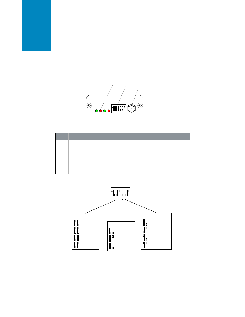
F i g u r e 1: N L 9 0 0 P R O S t a t u s L E D s
Status LEDs
DIP Switch
RPSMA Antenna Connector
ON
Pwr Link Rx Tx
1 2 3
4 5 6
T A B L E 2 : S T A T U S L E D S
L E D
C O L O R
D E S C R I P T I O N
Pwr
Green
On indicates that the unit is powered up.
Link
Red
On indicates that the Client unit(s) and Server unit are in range of
each other. Client units activate the Link LED when in Range of the
Server unit. Always lit on a Server unit.
RXD
Green
When flashing, indicates that the NL900PRO is receiving data.
TXD
Red
When flashing, indicates that the NL900PRO is transmitting data.
F i g u r e 2 : N L 9 0 0 P R O D I P S w i t ch S e t t i n g s
ON
1 2 3 4 5 6
Serial Interface
TX/RX Mode
1 2
5 6
RS232
RS232
RS485/422 Termination
3 4
Client, Addressed
Client, Broadcast
Forced 9600
2 wire
RS485
4 wire
RS485/422
None
2 wire RS485
termination
4 wire RS485/
422 termination
Server, Addressed
Server, Broadcast