R s 2 3 2 – RF Neulink NL900PRO User Manual
Page 7
C H A P T E R 3 - S E R I A L I N T E R F A C E
5
R S 2 3 2
RS232 is a single-ended data transmission protocol. The RS232 signals are represented by voltage levels
with respect to a system common (power/logic ground). The “idle” state (MARK) has the signal level
negative with respect to common, and the “active” state (SPACE) has the signal level positive with respect to
common.
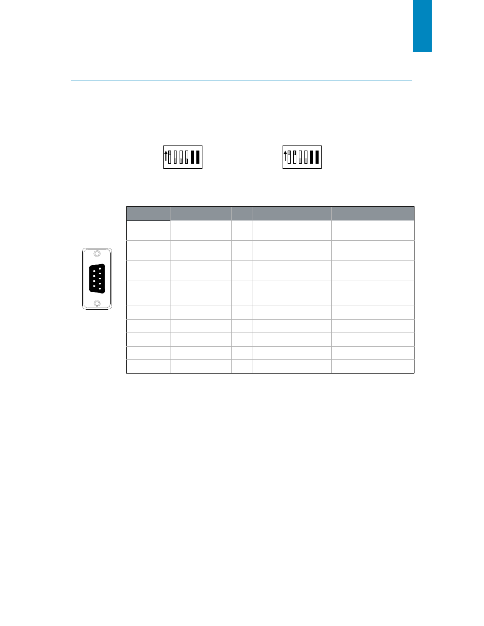
F i g u r e 3 : R S 2 3 2 D I P S w i t c h S e t t i n g s
ON
ON
1 2 3
4 5 6
1 2 3
4 5 6
Normal RS232 Operation
Forced 9600 Mode
T A B L E 3 : N L 9 0 0 P R O R S 2 3 2 P I N O U T
D B 9 P I N
S I G N A L N A M E
I / O
D E S C R I P T I O N
D E T A I L S
1
DCD
O
Data Carrier Detect
Carrier Detect Signal.
Connects to DSR (pin 6).
9
5
6
1
Female DB9
2
TXD
O
Transmitted Data
Serial Data from modem
to Host.
3
RXD
I
Received Data
Serial Data from Host to
Modem.
4
DTR
I
Data Terminal Ready
Used to determine if
modem is ready for
operation.
5
GND
-
Ground
Ground
6
DSR
O
Data Set Ready
Connects to DCD (pin 1).
7
RTS
I
Request To Send
Provides RTS Flow Control
8
CTS
0
Clear To Send
Provides CTS Flow Control
9
NC
-
No Connect
No Connect