Rms 8424s back panel, Power, Tally control port – RGBLink RMS 8424S User Manual User Manual
Page 25: Dvi+vga loop out, Panel instruction
Advertising
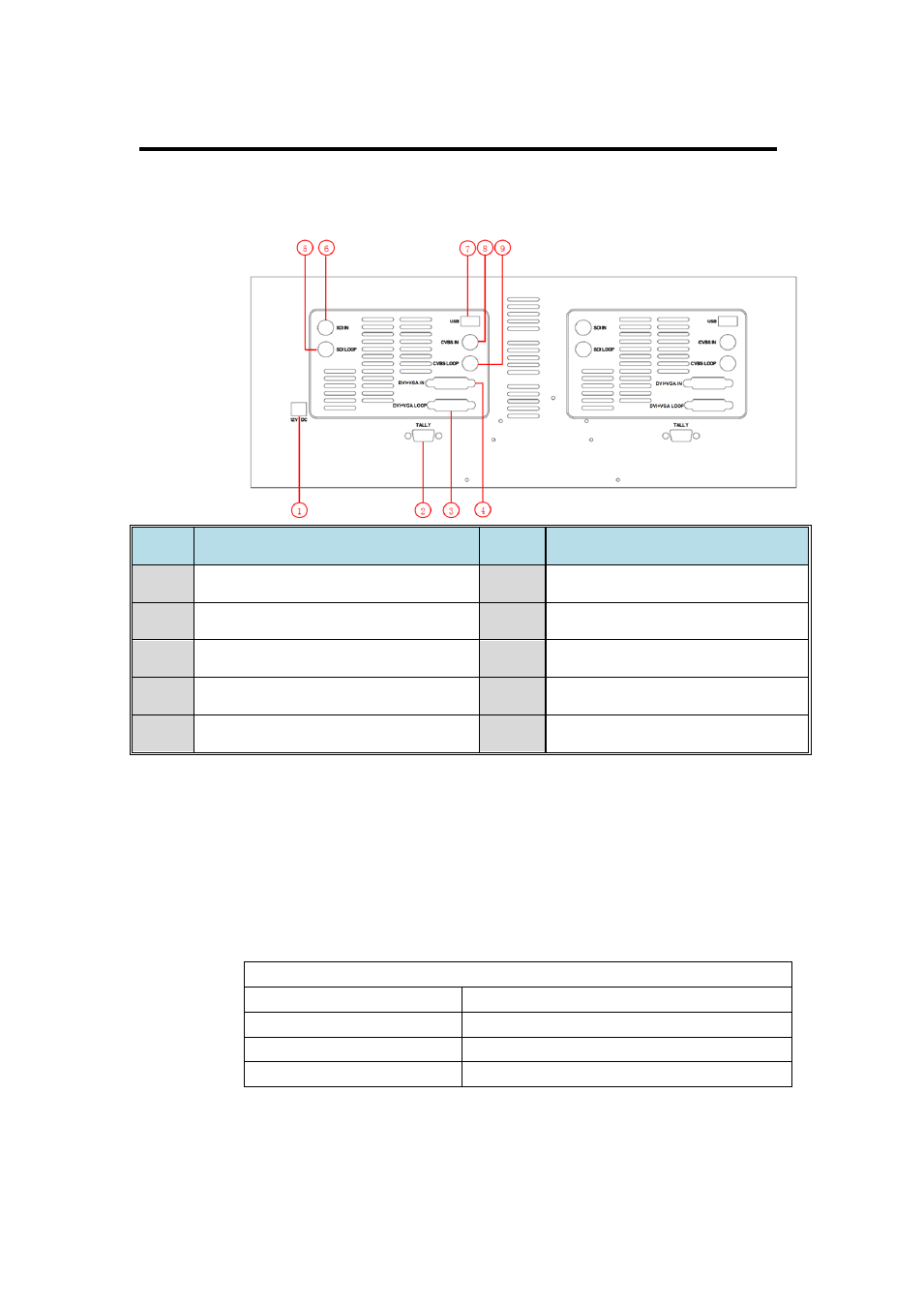
2. Panel Instruction
RMS 8424S Back Panel
RMS 8424S User Manual 25
Back view:
NO.
INTERFACE
NO.
INTERFACE
1
Power
6
SDI Input
2
TALLY Control Port
7
USB Port
3
DVI+VGA Loop Out
8
CVBS Input
4
DVI+VGA Input
9
CVBS Loop Loop Out
5
SDI Loop Loop Out
1. Power
DC 12V IN: Connect with DC12V power adapter. Power polarity is:
negative inside and cathode outside.
2. TALLY Control port
TALLY control port (RS-232). The electrical level is as follows:
Electrical level: ≤5V
Voltage
Tally light condition
≤0.5V
ON
≥1.3V
OFF
0.5V-1.3V
Indeterminate state
3. DVI+VGA Loop Out
DVI+VGA LOOP: DVI+VGA loop out port.
Advertising