Assembly, Kick wheel assembly – Skutt Kickwheel User Manual
Page 3
TAB TEXT HERE
TAB TEXT HERE
TAB TEXT HERE
TAB TEXT HERE
TAB TEXT HERE
K I C K W H E E L M A N U A L
rev 11/20/08
Assembly
Kick Wheel Assembly
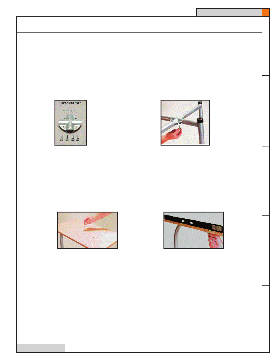
1. With Bracket A and the 4 smallest carriage bolts provided, bolt pieces 1 & 2 snugly
together (do not over tighten). Turn these pieces upside down for easy access to the
nuts. Use lock washers on the nut end of the bolts (see figure 1). For proper position-
ing of Bracket A, temporarily hold the foot rests (Piece 3) between the straight seat post
on Piece 2, and the sides on Piece 1, allowing 1/2" additional space between the end of
the foot rest and Piece 1 (see figure 2).
2. Thomas Stuart's design features a unique system for leveling its frame to uneven
floors. By pushing the 2 sides of Piece 1 closer to each other before tightening Bracket
A, you will eliminate the frame from rocking side to side. By pulling these 2 sides apart,
you will eliminate any rocking from front to back.
3. After positioning, tighten the nuts on Bracket A securely. Small wood pieces may
have to be placed under the legs on floors of extreme unevenness.
4. Using the 3 flat head machine screws provided, attach the table top (with the counter
sunk hole facing up) first to the holes in Piece 1, then the long screw in the front leg
of Piece 2 (see figure 3). The front leg of Piece 2 will be slightly shorter in height than
Piece 1. Only hand tighten the screw that inserts through the front leg. This is the only
bolt that does not have to be tightened all the way. It should only be tightened enough
to make the table tilt slightly away from the potter using the wheel.
Page 3