Fig. 4 fig. 5, Tournament rake assembly instructions – Smithco Super Star X-Treme Gas 43-000-x (sn 43375 – Current) Parts & Service Manual User Manual
Page 109
C-5
Rear Attachment
P
RO
B
RUSH
TOURNAMENT RAKE ASSEMBLY INSTRUCTIONS
Your
P
RO
B
RUSH
TOURNAMENT RAKE
comes mostly assembled.
1. Before assembly please note the two Brush/Finish Blade Assemblies (Refs A & C in Fig.1) that are
mounted on the outside (RH & LH) have flat washers that are between the Brush Arms (Refs 2 & 21) and
the Brush Arm Mount (Ref 6).
2. Also please note the placement of the Brush/Finish Blade Assemblies as illustrated in Fig 1. They must
be mounted as illustrated to work as intended.
3. Begin assembling your
P
RO
B
RUSH
TOURNAMENT RAKE
by inserting the Outside and Center Groomer Blade
Assemblies (Refs A, B & C in Fig.1) in their locations as illustrated. Secure the Outside Assemblies with
the ¼" Pin (Ref 11) and the Center Assembly with the ¼" x 1¾" Bolt and Lock Nut (Ref 13).
4. Mount the Brush/Finish Blade Assemblies to the Brush Arm Mounts (Refs 6, 30 & 15) as illustrated using
the
3
/
8
x 2½ Bolts and Lock Nuts. Assemble with the Springs (Ref 4) as shown in Fig. 2. Please note
that the
3
/
8
" Flat Washers are used only on the Outside Assemblies. Secure when assembled.
5. Mount your
P
RO
B
RUSH
TOURNAMENT RAKE
to the trap rake quick hitch. Position the Rake so it is centered and
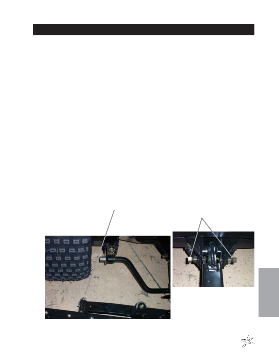
equal distance away from the right and left hand tires (2-3 inches). Fig. 4. Once positioned, set the
Adjustment Screws on the Hitch so they touch the trap rake hitch. Fig. 5.
6. Run machine and test for operation of the Rake by raising and lowering the assembly and with rake down
turn sharp corners in both directions to ensure rake is not contacting the tires. Test Rake in sand to
ensure tire tracks are covered when turning sharp corners. If the tire tracks are not covered by the Rake,
turn the Adjustment Screws on the Rake Hitch so the rake comes closer to the tires when turning. For
reference see Fig. 4 and 5 below.
NOTE:
The Outside Brush/Finish Blade Assemblies may be rotated 180° for transport and for working in narrow
areas, as illustrated in Fig.3 on the facing page.
Fig. 4
Fig. 5
Adjustment Screws
Minimum Gap ½"