Capswitcher – Southern States 38 kV-170 kV CapSwitcher User Manual
Page 4
Title:
Southern States 38 kV–170 kV
CapSwitcher
®
Vertical Interrupter Style Capacitor Switcher
Product Specification
Guide
Page 4 of 10
Publication No.: PSG-807-031109
3.02.03 Source Supply Voltages
Purchaser will supply the following sources for the motor, auxiliary, and
control circuits:
1. Motor / Control Voltage 48 VDC; 125 VDC; 250 VDC; 120 VAC, 60 Hz, 1∅;
or 240 VAC, 60 Hz, 1∅
2. Auxiliary Voltage 120 VAC, 60 Hz, 1∅ or 240 VAC, 60 Hz, 1∅
3.03 Resistors
The capacitor switcher shall be constructed with pre-insertion (closing) resistors
for damping transients caused by switching capacitor banks. The resistor
contacts and the main contacts shall make and break in SF
6
gas.
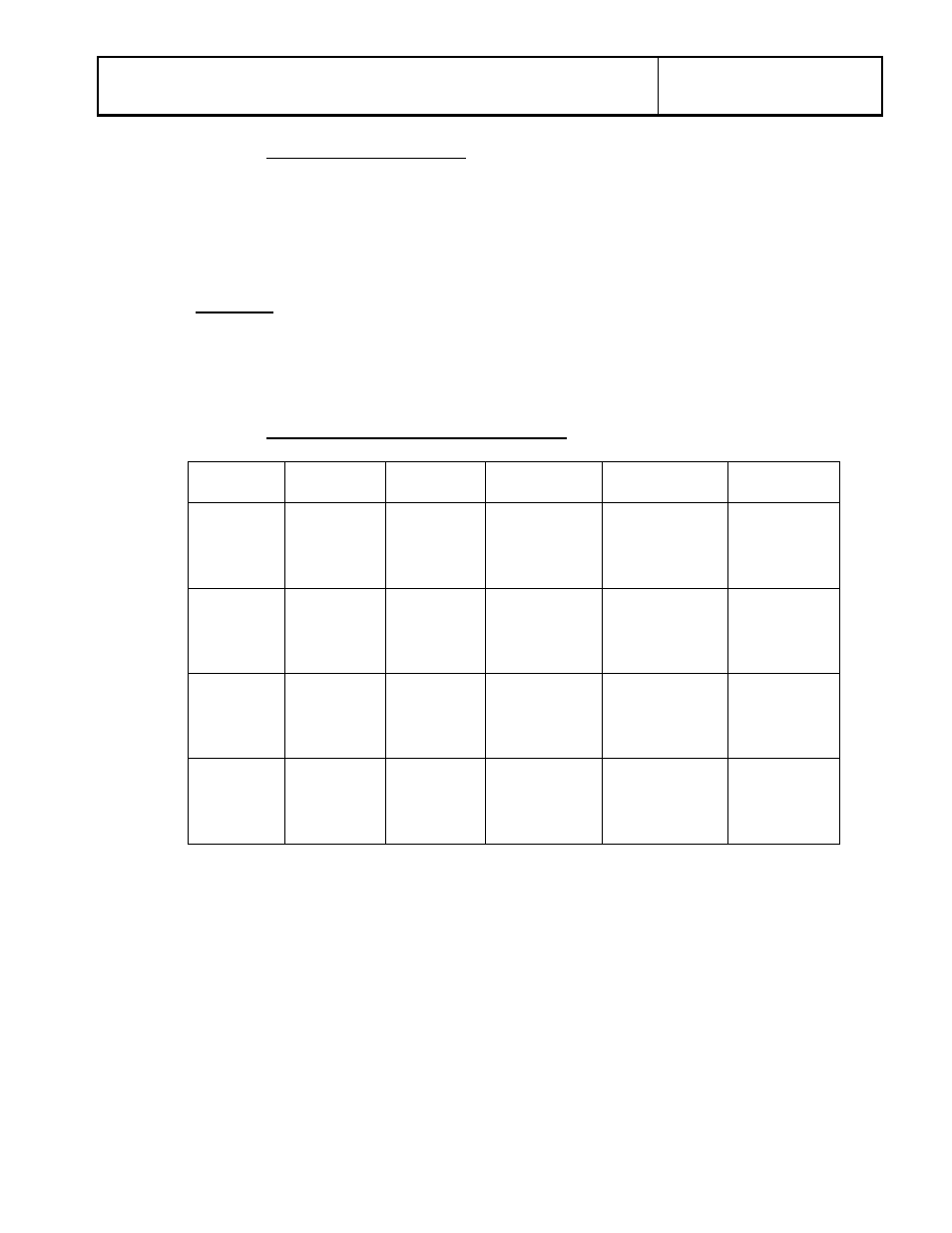
3.03.01 Resistor Values and Selection Chart
38 kV
48.3 kV
72.5 kV
123 kV
145 kV
170 kV
3 – 6
MVAR
90 Ω
4 – 18
MVAR
40 Ω
5 – 20
MVAR
80 Ω
15 – 40
MVAR
150 Ω
10 – 25
MVAR
300 Ω
18 – 30
MVAR
300 Ω
6.1 – 16
MVAR
30 Ω
18.1 – 48
MVAR
20 Ω
20.1 – 72
MVAR
40 Ω
40.1 – 75
MVAR
75 Ω
25.1 – 60
MVAR
150 Ω
30.1 – 75
MVAR
150 Ω
16.1 – 40
MVAR
12 Ω
75.1 – 130
MVAR
37.5 Ω
60.1 – 120
MVAR
75 Ω
75.1 – 181
MVAR
75 Ω
120.1 – 155
MVAR
37.5 Ω
The resistor must be able to withstand closing into a fault and continue to
perform its specified function without damage. Resistor insertion time shall be
between 5 ms and 15 ms. Resistors shall be optional for systems that do not
require transient over-voltage control or inrush current mitigation. The quotation
request will specify if resistors are to be supplied and their required ohm rating.
The resistor and interrupter must be contained in a common housing. The
interrupter must directly activate the resistor. Designs using separate housings
for the interrupter and resistor (or other transient suppression device) are not
acceptable. Designs that insert the transient suppression device in air are not
acceptable.