Performing a zero calibration, Performing a span calibration, Parts list and internal components – Super Systems Hydrogen Nitrider Analyzer User Manual
Page 7
Basic Nitriding Sampling System – Hydrogen Analyzer
Super Systems Inc.
Page 7 of 12
their respective percentages. The more similar to the process gas the calibration gas is, the more
accurate the calibration will be.
Performing a Zero Calibration
On the Sensor Calibration page, select “Zero Hydrogen”. Turn the valve on the side of the enclosure to
the “Calibration Gas” position, and attach the Zero gas to the “Calibration Gas Inlet” port. Begin the flow
of gas at a rate of 1.5 to 2.0 SCFH as measured on the flow meter on the door of the enclosure. The gas
should not be under any pressure other than the amount required to maintain the appropriate flow
amount. The target Value is shown on the screen. For a Zero Calibration, this will be 0.00 (the amount of
Hydrogen in the Zero Gas). The Measured H
2
Value can be seen at the bottom of the screen. When this
value comes to equilibrium, it will not be showing any upward or downward trends, only the slight
oscillation of the readings. This usually occurs in approximately 30 seconds. When the sensor is at
equilibrium, press the green “Calibrate” button to perform the zero calibration. After the Zero
Calibration is complete, turn off the flow of gas and disconnect it from the enclosure.
Performing a Span Calibration
To perform a span calibration, select “Span Hydrogen”, attach the Span Gas to the Calibration Gas Inlet
port, and begin the flow of gas at 1.5 to 2.0 SCFH. The Target Value should be set to the exact amount of
Hydrogen that is in the Span Gas cylinder. Then the same procedure should be followed as the Zero
calibration, with the “Calibrate” button being pressed after the readings reach equilibrium. After the
Span Gas calibration is complete, turn off the flow of gas, disconnect the cylinder from the enclosure, and
restore the valve on the side of the instrument to the “Sample Gas” position. This will re-connect the
sensor to the process gas stream.
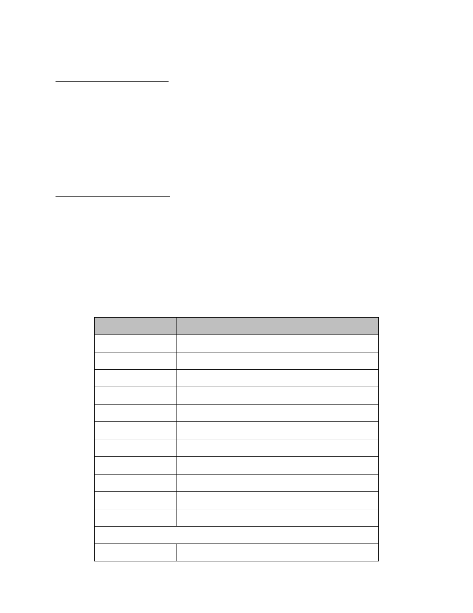
Parts List and Internal Components
The following items can be purchased as needed for the Hydrogen Nitrider Analyzer.
Part Number
Description
31604
2 GB SD card
37026
Fan (24VDC, 60mm)
37029
Fan filter assembly
37150
3-way ball valve
37050
High capacity bowl filter
37051
High capacity filter element
34444
Tubing
33097
Circuit breaker
31135
Power supply
A20624
Hydrogen sensor
31296
3.5” touch screen
Full Unit
15357
Hydrogen Nitrider Analyzer