Wall plate controller, Rp2 (connects to rj2) – SVS 7 110V User Manual
Page 11
the toggle switch stops the Lift. This is designed as a safety feature. The key switch is an extra precaution, when
the key is removed, the Lift is secure.
b. Connecting a Touch Screen Controller (External Controller)
The simplest external controller connections are to use the White wire (pin 1) as the common and the Brown
wire (pin 3) for down to Show position and the Red wire (pin 2) for up. For this and other wiring options please
refer to the external controller wiring diagrams in the Appendix. Also:
1. Program a release of relays to stop the Lift on up and down positions
2. Program a time out after the normal runtime, 2 seconds max. (SVS Lifts raise/lower at 1-inch/second.)
3. Program an exclusive lockout on up and down so that both cannot be activated at the same time. (Note:
SVS Lifts have a lockout function that disables the Lift when it receives a up and down command at the
same time. Removing one of the two commands releases the lockout condition.)
4. Hold relays on to raise/lower the Lift.
5. Never leave voltage on the up and down. Always program a release after the travel time has been
achieved.
If you have any questions please contact SVS for proper wiring.
SVS 7 Lift Installation Instructions
Page 11 of 18
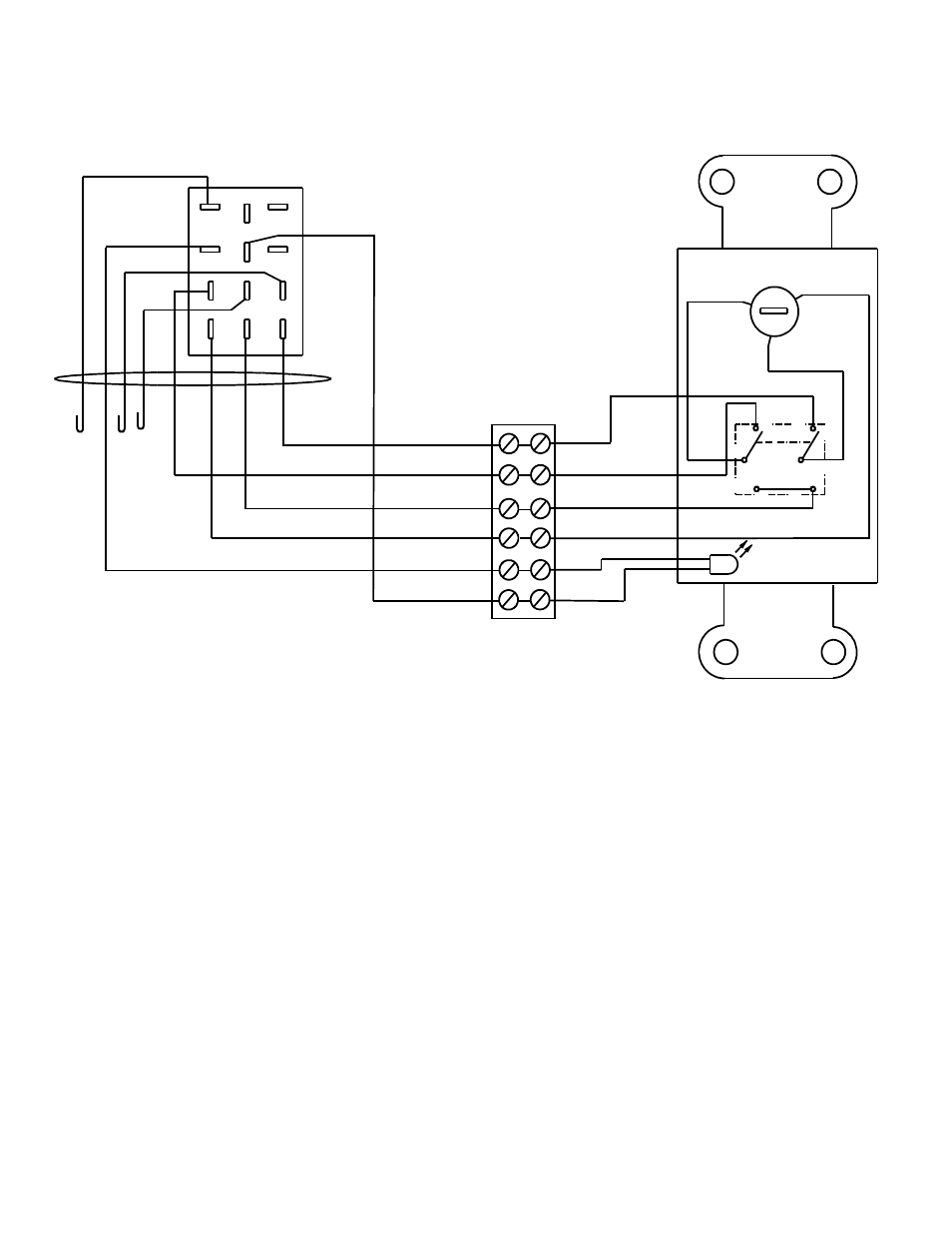
Figure 9. Wall Plate Controller Wiring Diagram
VIEW FROM BACK
(24vac)
+
-
(SERVICE)
C
2
1
GRN BRN
UP
PUR
BLK
BLU
WHT
MOTOR
POWER ON
WHT
DOWN
SHOW-OFF-SERVICE
RP2 (CONNECTS TO RJ2)
YEL
(SHOW)
RED
WHT
ORN
BLK
GRN
RED
WHT
BLK
ORN
GRN
BRN
BRN
3
2
1
4
5
6
9
8
7
12
11
10
WALL PLATE CONTROLLER