SVS 7 110V User Manual
Page 15
7. Make one and a half turns around the cable reel counter clockwise with your cable. Lock your cable in
the same way as in Step 6, to the two remaining holes (180
°
from the first holes used.)
8. Clamp your cable securely to the outrigger on the bottom frame of the Lift.
9. Run the Lift up and down to check the slack in your cable. Your cable will be slacked at the top of the
Lift when the Lift is in a full up position, and equally slacked at the bottom in a full down position.
Note: The Cable Retractor is located near the center of the scissors, but due to different number of scissors and
the opening time of the scissors, there can be slack in your cable above or below the cable reel as the Lift
lowers. Excess slack can be removed by adjusting the cable clamping on the cable reel after tracking the Lift up
& down. If the slack is adjusted correctly, the cable will be more even when in the up and down positions, with
slack occurring only in the middle position.
10. When proper cable tension is achieved, you can securely tighten the tie-wraps.
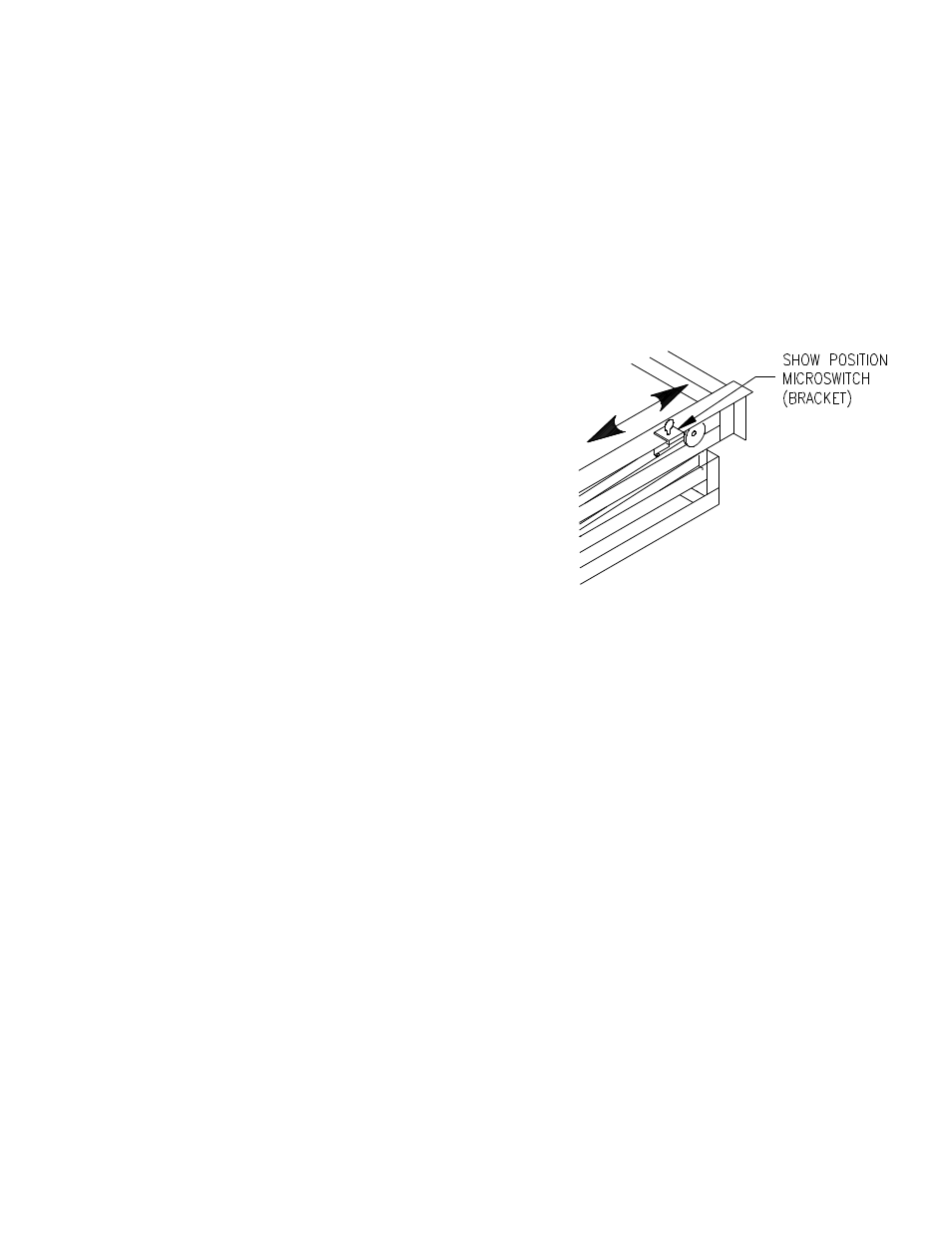
12. SETTING THE SHOW POSITION
The Show position is adjusted by positioning the Show position
microswitch located on the rear right of the Lift's top frame so that
the large roller washer compresses the Show position switch when
the Lift reaches the Show position.
1. Place the key switch in the Service position and lower the
Lift to the desired Show Position.
2. Loosen the thumb screw holding the Show microswitch
(bracket) in place and slide the Show microswitch
(bracket) along the Lift frame until the large roller washer
compresses the microswitch. You should hear a slight click
as you position the microswitch over the washer and the microswitch is compressed.
3. Moving the Show microswitch toward the rear of the Lift raises the Show position and moving the
Show microswitch toward the front of the Lift lowers the Show position.
4. Tighten the thumb screw. Make sure that the microswitch is not positioned too close to the washer
because the washer must be able to pass under the microswitch to reach the Service position.
5. The Show position is now set. Raise the Lift to a closed position and place the key switch in the Show
position and press the toggle switch down. The Lift will lower and stop at the Show position you set. It
maybe necessary to repeat steps 1 through 3 to get the Show position set where you want it.
6. The Lift will only stop at the Show position when lowering from above the Show position and not when
rising from below the Show position.
7. The Show position is adjustable with an accuracy of
+
/- 1/8-inch (0.32 cm).
13. MAINTENANCE AND ADJUSTMENTS
a. Maintenance
•
Inspect the Lift occasionally for any loose bolts or cable clamps. The scissor bolts are adjusted for no
slack, but must not be too tight. If scissor bolts are found loose, tighten to approximately 151 lbs torque,
the back off 1/8-inch. These bolts have nylon locking nuts and should stay at this position.
•
Check Lift and projector cables for damage or wear.
•
Check the Drum Lock Assembly to see if the Drum Lock solenoid energizes and raises the Drum Lock
arm when you press the Down toggle switch to lower the Lift. At all other times the Drum Lock
solenoid is de-energized and the Drum Lock arm stays in its down position. If the solenoid does not pull
up, the microswitch will not allow the motor to turn when to lowering the Lift.
•
Check the Drum Lock pawl (white nylon piece) located on the Cable Drum. The pawl should move
freely and drop when when it reaches the top of the Cable Drum's rotation, avoiding contact with the
SVS 7 Lift Installation Instructions
Page 15 of 18
Figure 13. Show Position Adjust