SVS 7HSE 110V User Manual
Page 8
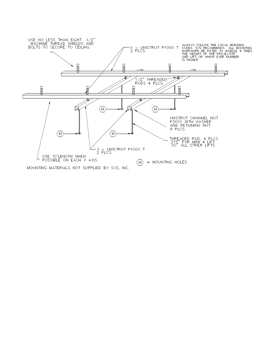
If the ceiling clearance allows, an “X-Y” or a cross-supporting structure is strongly suggested as shown in
Figure 6 Recommended Lift Support Structure for Flat Ceilings. This allows for front-to-back and side-to-side
adjustments of the Lift for alignment to the screen.
Important
When attaching the Lift to a flat concrete ceiling, SVS suggest two (2) pieces of P1000T Unistrut (or
equivalent) approx. 10-feet (3.04 m) long, to be installed on the ceiling first. Proper spacing between the two
pieces will be based on the distance between the four (4) mounting holes of the Lift as shown in Figure 4.
You should use at least four (4) 1/2” bolts and anchors evenly spaced on each piece of Unistrut to distribute the
weight of the supporting structure. Attach the two lower pieces of Unistrut to the upper two pieces of Unistrut
using 1/2” threaded rods to the Unistrut, using Unistrut P3010 1/2” channel nuts in the channel, along with a
locking washer and nut below the channel to lock into place.
IMPORTANT
If you are installing an Accessory #2 Plenum Shroud or Accessory #12 Decorative with the Lift, please
read the Accessory Installation Instructions before beginning your installation. The Lift support structure
will need to allow enough space for the Plenum Shroud and/or Decorative Cover mounting hardware
7. LIFT INSTALLATION
a. Preparation:
1. The Lift is shipped in a wooden crate.
2. Do not remove the Lift from the crate until you are ready to install the Lift..
3. The Installation Instructions, Wall Plate Controller with control cable, and projector mounting hardware
are located in a cardboard box inside the crate.
4. Unbolt the Lift from the bottom of the crate to remove the lift from the crate.
SVS 7HSE Lift Installation Instructions
Page 8 of 16
Figure 6 Recommended Lift Support Structure for Flat Ceilings