Names and functions of parts (display), Eslink – Teac GRANDIOSO D1 User Manual
Page 11
11
11
En
gl
is
h
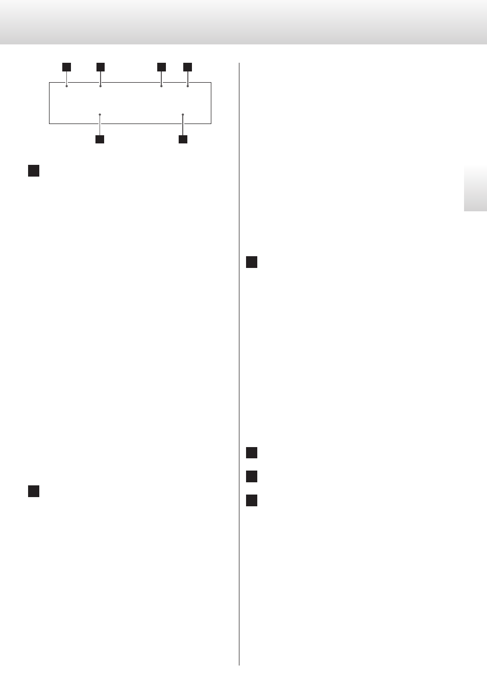
a
Channel
This shows the channel played back by this unit (page 15).
No indicator:
No channel has been set for this unit. Use this setting only with
mono output from a source device.
Lch:
This unit is set to the front left channel. By connecting the L-R
connectors of this unit and the D1 set to Rch, they can share var-
ious settings and during stereo output the right channel audio
signal from the audio source device can be sent to the Rch D1.
Rch:
This unit is set to the front right channel. By connecting the L-R
connectors of this unit and the D1 set to Lch, they can share vari-
ous settings and during stereo output the right channel audio
signal from the audio source device can be sent to this unit for
playback.
Cch:
This unit is set to the center channel. Use this setting when play-
ing back multichannel audio from an SACD connected by i.LINK.
SWch:
This unit is set to the subwoofer channel. Use this setting when
playing back multichannel audio from an SACD connected by
i.LINK.
LSch:
This unit is set to the surround left channel. Use this set-
ting when playing back multichannel audio from an SACD
connected by i.LINK.
RSch:
This unit is set to the surround right channel. Use this set-
ting when playing back multichannel audio from an SACD
connected by i.LINK.
b
Upconversion setting
No indicator:
The upconversion function is not in use.
UPCONV 2Fs:
The upconverter circuit will upconvert the signal to 64, 88.2 or
96 kHz before digital to analog conversion.
UPCONV 4Fs:
The upconverter circuit will upconvert the signal to 128, 176.4 or
192 kHz before digital to analog conversion.
UPCONV 8Fs:
The upconverter circuit will upconvert the signal to 256, 352.8 or
384 kHz before digital to analog conversion.
UPCONV DSD:
The upconverter circuit will convert the PCM signal to a DSD sig-
nal before digital to analog conversion.
DSD DIRECT:
If DSD_F (DSD filter) is set to OFF, this appears when a DSD signal
is input.
o
Even if the upconverter is set, the upconverter might not be
usable depending on the input source sampling frequency
conditions.
o
You can make settings as you like for each input.
o
When ES-LINK input is selected, this can only be set to OFF or
DSD.
c
Clock mode
No indicator:
CLK is set to OFF.
CLK OUT:
Shown when CLK is set to OUT.
The frequency display area shows the output clock frequency.
CLK IN:
Shown when CLK is set to IN.
The frequency display area shows the input clock frequency.
MCK IN:
Shown when CLK is set to MCK IN or MCK10M.
The frequency display area shows the input clock frequency.
INTERNAL:
This is shown when unsynchronized signals are received dur-
ing USB input and during playback with flow rate control when
using i.LINK input.
The frequency display area shows the master clock frequency
being used.
d
Clock frequency
e
Input
f
Sampling frequency
Names and functions of parts (display)
3 5 2
DSD DIRECT
MCK IN 10MHz
L c h
ESLINK
a
b
c
d
e
f