6 mounting, Electrical connection, 4 electrical connection – Tecfluid TH7 User Manual
Page 7
7
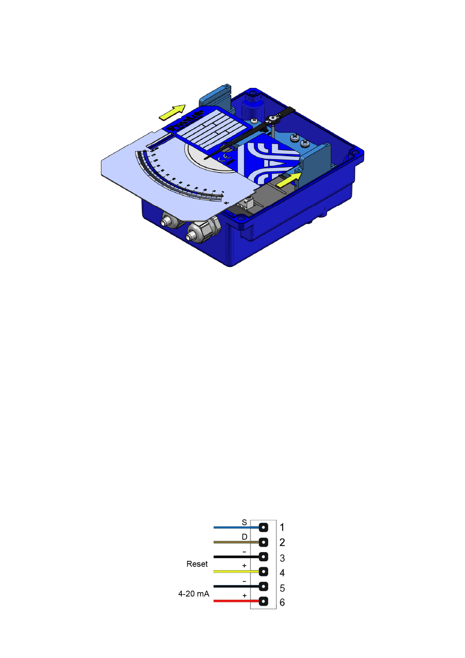
3.6 Mounting
Slide the scale plate through the top slot until it stops as shown in the figure.
Reassemble the cover with the four screws "Allen" M5 and the plastic washers.
4 ELECTRICAL
CONNECTION
For the electrical connection, the transmitter has a screw terminal strip.
For the electrical installation it is recommended to use multiple conductor cables with
individual cable sections in the order of 0.25 to 0.5 mm
2
in order to make it easier to
connect.
A twisted pair wiring should be used to avoid electrical interferences in the 4-20 mA loop.
In some instances, shielded cable may be necessary.
Before starting the installation, check that the cable glands are the right size for the cables
to be used, this will guarantee the instrument will stay watertight. The M16x1.5 cable
glands used are for cables with outside diameters between 6 mm and 10 mm.
Peel the outside insulation to free the inner cables. It is recommended to tin the ends of
the wires to avoid loose ends. Pass the cables through the cable glands and screw down
in the corresponding positions of the terminal strip. Once the wiring is finished make sure
that the cables are well gripped by the cable glands to maintain the degree of protection.
The cable glands must be always closed. Entry of dust or some types of vapors can
damage the internal system of bearings and therefore the equipment.
To help in the wiring of the equipment, the description of the terminals is marked on the
printed circuit next to the terminal strip.
Pulses