Network -9 power connection -9, Network, Power connection – Verilink PRISM 3021 (34-00262) Product Manual User Manual
Page 17
Installation 2-9
PRISM 3021
and (A) NMS OUT ports. The different connection methods
are described in the following paragraphs.
NMS IN
AND
NMS OUT
The two 6-pin modular connectors labeled (A) NMS IN and
(A) NMS OUT may be used for connection to the 8100A Site
Controller. This port is configured to allow the connection of
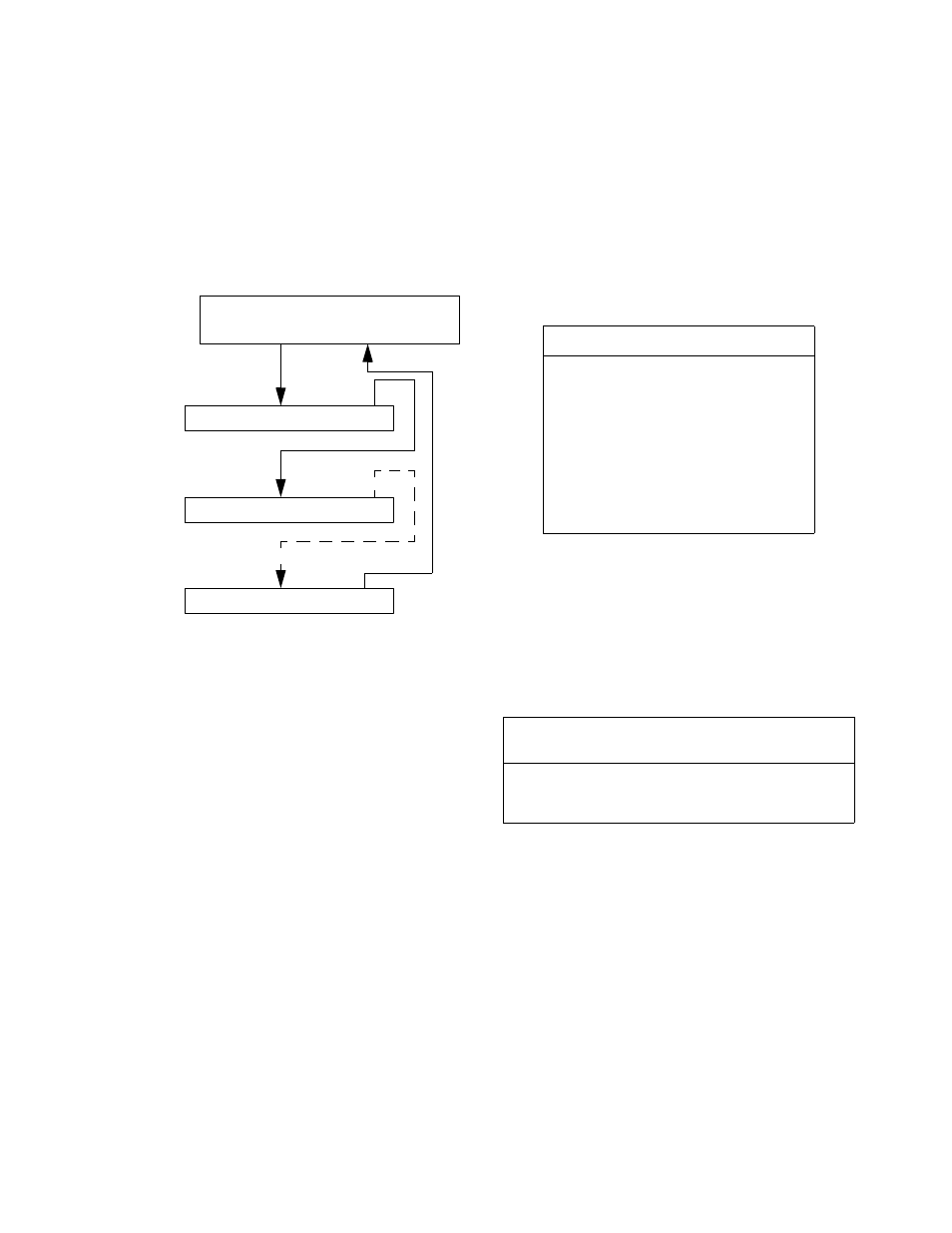
multiple collocated units in a daisychained IN/OUT bus
arrangement as shown in Figure 2-10. The OUT port of one
element is connected to the IN port of the next element, and
so on, to form a complete chain among the group of elements.
All units on the same NMS chain must use the
same NMS bit rate and have different addresses
(see NMS Port Rate on page 2-3, Switch S2 on
page 2-3, and Switch S3 on page 2-3).
NMS S
PLIT
C
ABLE
The 8100A Site Controller may be connected directly into the
NMS chain between two elements. A Y-cable is used from
the 8100A serial port which splits the transmit and receive
signals into two 6-pin modular connectors for the (A) NMS
IN and (A) NMS OUT ports. Ordering information for this
cable is found in Ordering Numbers on page 1-3.
NMS IN
The (A) NMS IN connector provides both the transmit and
receive signal pair. This port may be used for a modem con-
nection or as a VT100 terminal interface (see Terminal
Interface Layout on page 4-1).
NMS OUT
The (A) NMS OUT connector only provides the receive sig-
nal pair.
C
HASSIS
O
PERATION
8100A Site Controller operation has the units chained
together. The front panel supervisory port and the rear panel
NMS ports operate in the same fashion.
The NMS address, port rate, and power up configuration
mode may be set by either configuration switches or through
software control. The physical connection is a 6-pin modu-
lar connector with the pinouts for these connectors shown in
Table 2-W. This port is a serial RS-232 DCE port config-
ured for eight bits, no parity, and one stop bit.
Network
The PRISM 3021 has four styles of network adapter cables:
a 75-ohm BNC, and a 120-ohm twinax, a 120-ohm RJ-48,
and a 120-ohm DB-15. The BNC and twinax connectors are
standard. The pinouts for the RJ-48 and DB-15 connectors
are given in Table 2-X.
Power Connection
The 3021 requires a -48 VDC power source capable of sup-
plying a 150 -mA current. All units in the chassis are pow-
ered by -48 VDC sources which are connected to the 6-
position terminal strip, TB2, on the rear of the 1051 chassis.
The power supply should be sized for maximum current
draw for the chassis.
The 1051 chassis is designed with two power buses. The A
bus feeds the odd slots and the B bus feeds the even slots. A
power board is installed on TB2 which allows the connec-
tion of two independent -48 VDC supplies operated in
redundant mode. This is the default configuration described
in Redundant Power Source below. The other powering
method is described in Single Power Source.
Figure 2-10 NMS Daisychain Arrangement
NMS OUT IN/OUT (standalone)
OUT IN (nest-mount)
8100A
NMS IN OUT
Element #1
NMS IN OUT
Element #2
NMS IN OUT
Last Element
Table 2-W NMS Port Connector Pinouts
Pin
(A) NMS Bus IN (A) NMS Bus OUT
1
Not Used
Not Used
2
Signal Ground
Signal Ground
3
Data Out
Data Out
4
Data In
Not Used
5
Signal Ground
Signal Ground
6
Not Used
Not Used
Table 2-X Network Connector Pinouts
Connector
Type
Tip
Input
Ring
Input
Tip
Output
Ring
Output
Ground
RJ-48
1
2
4
5
7, 8
DB-15
3
11
1
9
2, 4