Enter the sensor settings – Wavetronix SmartSensor Matrix (SS-225) - Quick-reference Guide (User) User Manual
Page 2
4
Lane configuration option 1: automatic configuration
These settings are found under Sensor Settings on the SSMM main menu.
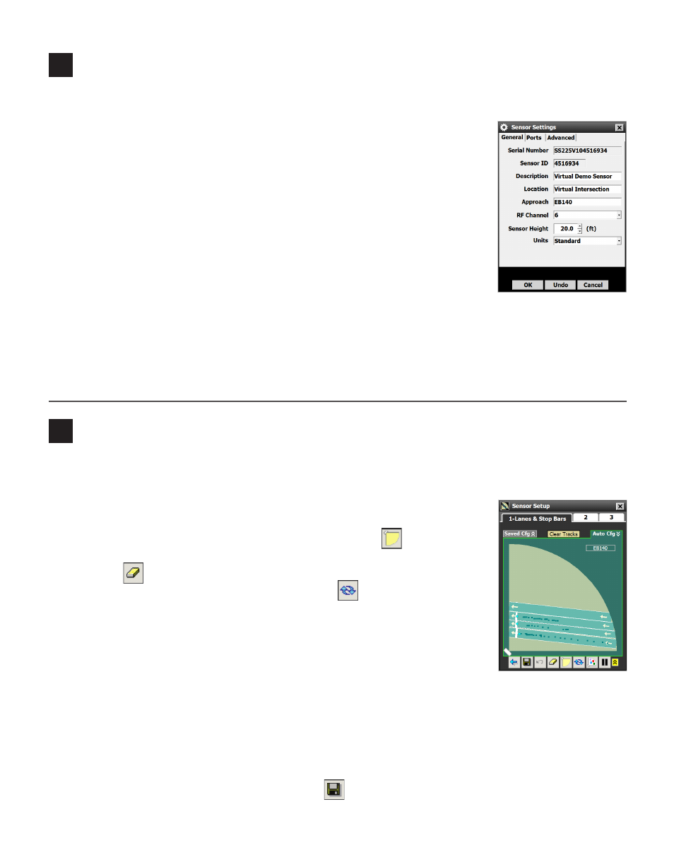
General Tab
˽
Serial Number – The sensor’s serial number; cannot be edited.
˽
Sensor ID – Used to uniquely identify all sensors on a multi-drop bus; by de-
fault is the last seven digits of the sensor’s serial number and cannot be edited.
˽
Description/Location/Approach – For identification/information. Descrip-
tion and Location are limited to 64 characters, Approach to 32 characters.
˽
RF Channel – Setting sensors to different channels prevents radars from
interfering with each other.
˽
Sensor Height – In feet; affects the display of data in SSMM.
˽
Units – Choose between Standard or Metric.
Ports Tab
˽
Response Delay – Allows you to configure how long the sensor will wait before responding to a mes-
sage received. The green arrow points to the port over which you are currently connected.
˽
Data Push – Lets you set over which port data is being pushed.
˽
Source – Choose between Antenna and Diagnostic.
Use the following steps to auto-configure the SmartSensor Matrix:
1 Select Sensor Setup from the SSMM main menu. The Sensor Setup screen
will appear. If the Lanes & Stop Bars screen is not already open, click on tab 1
to open it.
2 Move the sensor to the desired orientation by clicking the
button (bot-
tom of screen).
3 Click the
button to clear the edit area.
4 Start automatic lane configuration by clicking the button and selecting
Restart Auto Lane Cfg from the window. Allow the intersection to cycle at
least twice before proceeding (this could take several minutes).
Note. To see your automatically configured lanes, you must have your display set
to Automatic Configuration overlay (click the Auto Cfg tab at the top right of the
screen).
5 Once the automatically configured lanes have appeared, capture the lanes and stop bars. To capture, click
once on a lane to highlight it, and then again to bring up the Capture Lane window. Select Capture Lane or
Capture All. Any stop bars in the captured lanes will be captured as well.
6 Make manual adjustments, if necessary (see Part 5).
7 Save your changes to the sensor by clicking the
button.
3
Enter the sensor settings