Map zones to channels, Verify your configuration, Optional: use tools – Wavetronix SmartSensor Matrix (SS-225) - Quick-reference Guide (User) User Manual
Page 4
WX-500-0173
© 2015 Wavetronix LLC. All rights reserved. Protected by US Pat. Nos. 6,556,916; 6,693,557; 7,426,450; 7,427,930; 7,573,400; 7,889,097; 7,889,098; 7,924,170; 7,991,542; 8,248,272; 8,665,113;
and Cdn. Pat. Nos. 2,461,411; 2,434,756; 2,512,689; and Euro. Pat. Nos. 1435036; 1438702; 1611458. Other US and international patents pending. Wavetronix, SmartSensor, Click, Com-
mand and all associated logos are trademarks of Wavetronix LLC. All other product or brand names as they appear are trademarks or registered trademarks of their respective holders.
Product specifications are subject to change without notice. This material is provided for informational purposes only; Wavetronix assumes no liability related to its use.
7
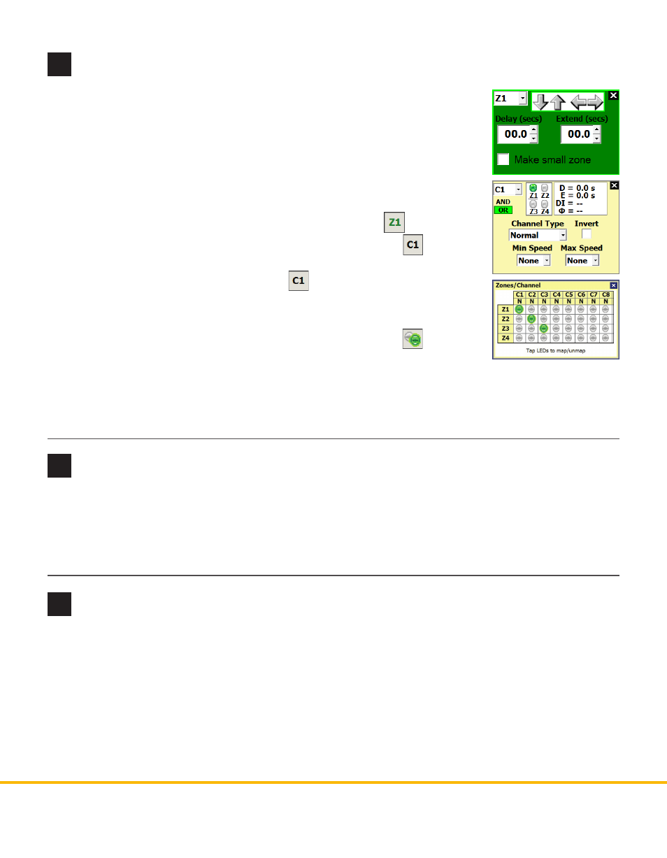
Map zones to channels
If you have automatically placed zones, the first four are mapped to C1–C4,
respectively. You can also manually map zones to channels. Zones can be mapped
to channels in three different ways.
Note. You can map multiple zones to the same channel. When multiple zones
are mapped to the same output channel, the zone detections are “or”-ed together,
meaning that if any of the zones associated with a channel is active, then the
channel output will be active.
˽
Edit Zone window – To move a zone, select it and click on the
button.
˽
Edit Channel window – To map a certain channel, click on the
button.
Click on one of the gray indicators marked Z to map the zone to the channel.
To select a different channel, click on the button to cycle through until
the desired channel appears. To add Delay, Extend and Phase infomation,
click anywhere on the right side of the window.
˽
Zones/Channel map – To see all channels and zones, click the button.
Click on the indicators in the table to map or un-map zones and channels. A
zone is mapped to a channel if the corresponding indicator is green; it is not
mapped if the indicator is gray.
Once you’ve finished, click to save your changes to the sensor.
8
Verify your configuration
9
Optional: use tools
1 Select tab 3 to open the Verification screen.
2 Verify the sensor is configured and working properly: the blue rectangles indicate detections; the indi-
cators at the top light up red when the associated channel is active. To see the zones associated with a
channel, click on that channel’s indicator.
The following are available under the Tools option on the main menu.
˽
Backup/Restore – Allows you to create a backup of your sensor configuration, restore a sensor configu-
ration from a backup file, or reset your sensor to factory defaults.
˽
Sensor Diagnostics – Allows you to run tests to verify whether the sensor is working properly.
˽
Tracker Logging – Logs vehicle detections as they’re tracked through the sensor’s view.