Westermo DDW-226 User Manual
Page 7
7
6642-22402
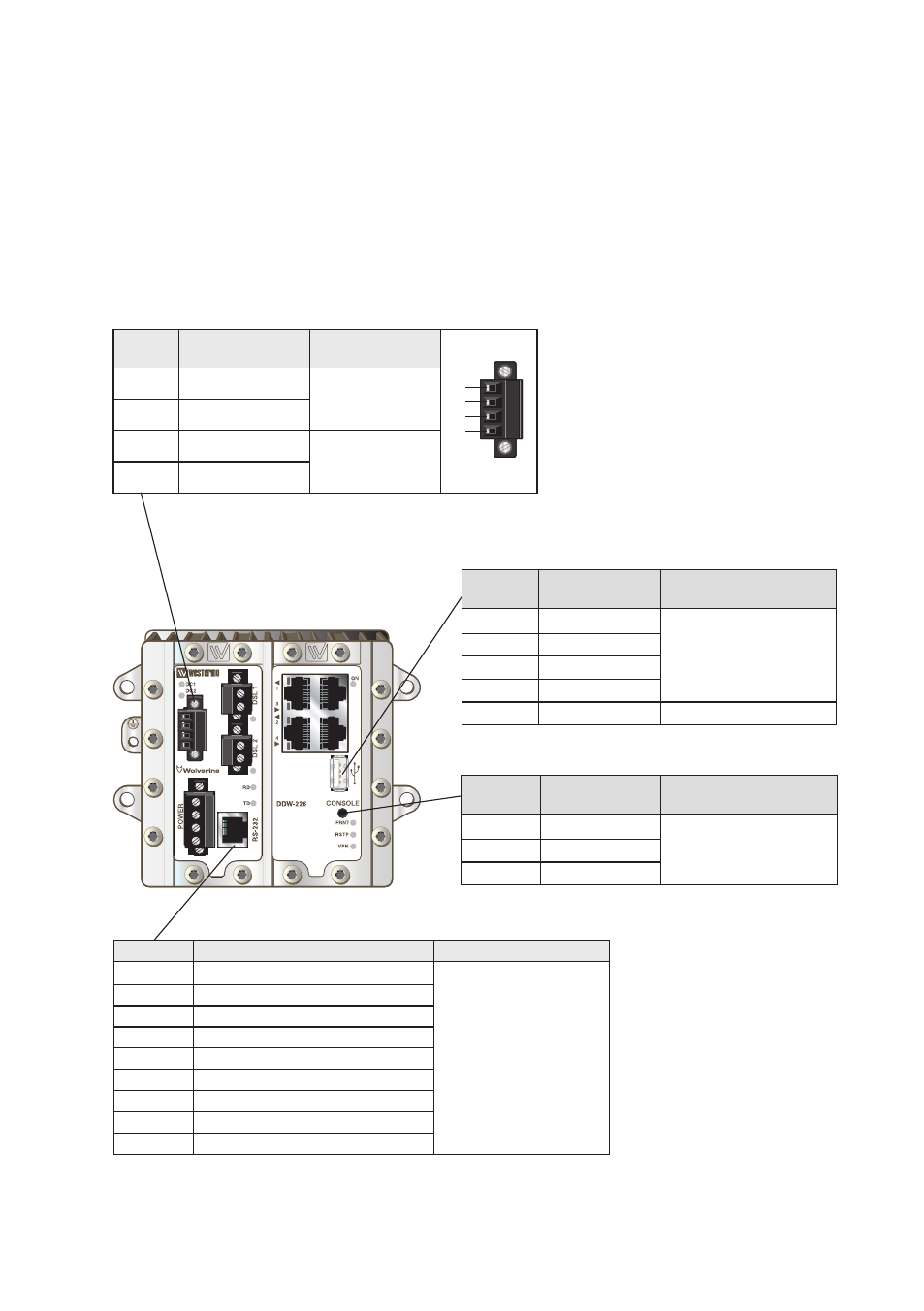
Position
Direction*/
description
Input/Output
values
1
2
3
4
1
IO / Relay output + U
in
= 60 VDC max
U
in
= 80 mA max
2
IO / Relay output –
3
IO / Digital in +
U
in
= 60 VDC max
U
in
= 10 mA max
4
IO / Digital in –
Position
Direction/
descripton
Input/Output
values
1
In/out / GND
U = 3.3 VDC max
I = 24 mA max
2
Out / Tx
3
In / Rx
Position
Direction/
descripton
Input values
1
Out / VBUS
U
out
= 5 VDC max
I
out
= 500 mA max
2
In/out / D–
3
In/out / D+
4
GND
Shield
PE
Position
Descripton
Input/Output values
1
Out / Data Set Ready (DSR)
U
max
= ± 12 Vpk
I
max
= ± 60 mA
Data rate:
0.3 – 115.2 kbit/s
2
Out / Data Carrier Detect (DCD)
3
In / Data Terminal Ready (DTR)
4
In/Out / Signal Ground (SG)
5
Out / Receive Data (RD)
6
In / Transmit Data (TD)
7
Out / Clear To Send (CTS)
8
In / Request To Send (RTS)
Shield
In/Out / Connected to PE