Functional description, Block diagram, Wire 2-wire – Westermo TD-29 User Manual
Page 11
Advertising
11
6611-2002
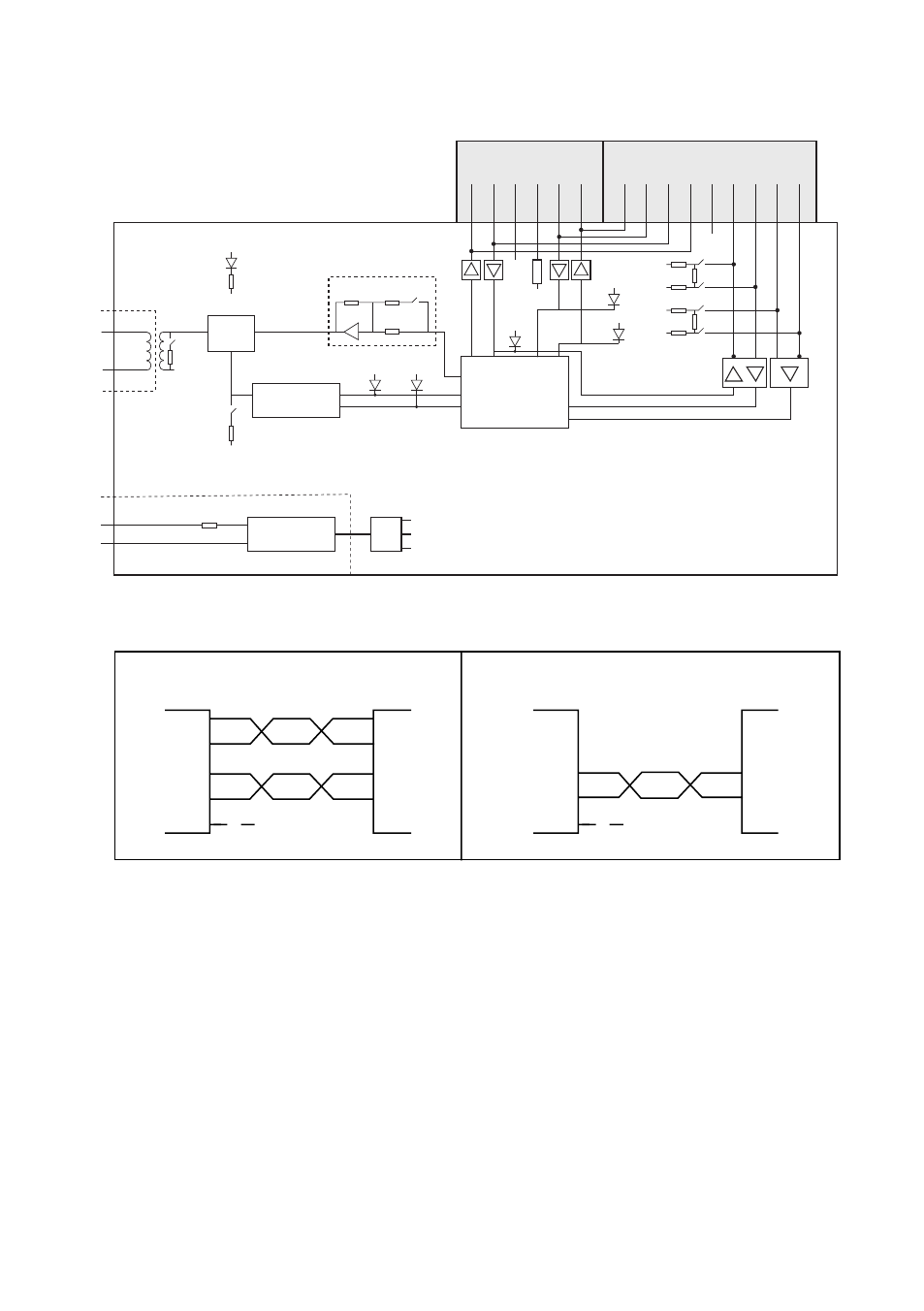
Functional description
Block diagram
Amplifier S1:6
S1:7
CTS
RD TD SG
RTS
RTS LED
CTS LED
TD LED
RD
LED
DCD
LED
DSR
CTS
RTS TD RD SG B A B’ A’
Screw terminal
D-Sub
1
2
3 4 5
6 7 8
2
3
5
0V
0V
F1
0V
+5V
–5V
0V
S2:4
S2:3
S2:2
S2:1
5V
0V
5V
0V
5V
6 7 8
9
MCU
FSK
Demodulator
Isolated
Power Supply
S1:4
0V
0V
PWR
LED
Line
switch
Line
Power Supply
RS-422/485 connection
4-wire
2-wire
9
8
7
6
5
7
6
5
A’
B’
A
B
A
B
A’
B’
Receiver
Receiver
A/A’
B/B’
B/B’
A/A’
Twisted pair
Twisted pair
TD-29
TD-29
Transmitter
Transmitter
RS-422
equipment
RS-485
equipment
Transmitter/
Receiver
Transmitter/
Receiver
NC
NC
Advertising