Safety control drawing – Westermo RFI-2xx User Manual
Page 6
6
6641-22310
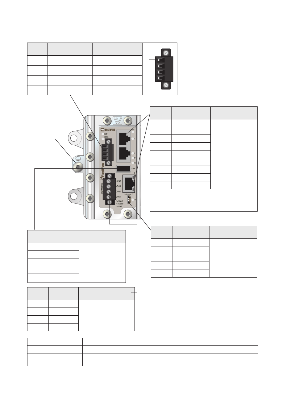
M5 threaded hole
for PE connection
Safety control drawing
Position Direction /
description
Input / Output values
1
2
3
4
1
IO / Status +
U
in
= 60 VDC max
2
IO / Status –
I
in
= 80 mA max
3
IO / Digital In +
U
in
= 60 VDC max
4
IO / Digital In –
I
in
= 2.9 mA max
Position Direction /
description
Output values
1
Out / VBUS
U
out
= 5 VDC max
I
out
= 500 mA max
2
In/Out / D–
3
In/Out / D+
4
GND
Shield
PE
Position Direction /
description
Input values
1
In / +DC1
U
in
= (16 – 60) VDC
I
in
= 2.0 A @ 16 VDC
P
In
= 31.5 W @ 16 VDC
2
In / +DC2
3
In / COM
4
In / COM
Position Direction /
description
Input/output values
1
In/Vbus
U = 5V VDC max
I = 100 mA max
2
In/Out D-
3
In/Out D+
4
Not connected
5
GND
Degree of protection:
IP 40
Ambient temperature:
–40 °C to +70 °C
Installation spacing:
Minimum 25 mm above/below
Minimum 10 mm left/right
Position Direction /
description
Input/output values
1
In/Out / BI_DA+
Per port:
U = ± 1 V (4V/us)
I = ± 20 mA
Data rate:
10/100/1000 Mbit/s
2
In/Out / BI_DA–
3
In/Out / BI_DB+
4
In/Out / BI_DC+
5
In/Out / BI_DC–
6
In/Out / BI_DB–
7
In/Out / BI_DD+
8
In/Out / BI_DD–
Shield
PE
Galvanically isolated via signal transformers and
capacitively isolated to GND/PE through a 2kV
1000pF capacitor.
See user manual for proven transient protection.