Deflector line – X-Treme Audio Deflector Line User Manual
Page 5
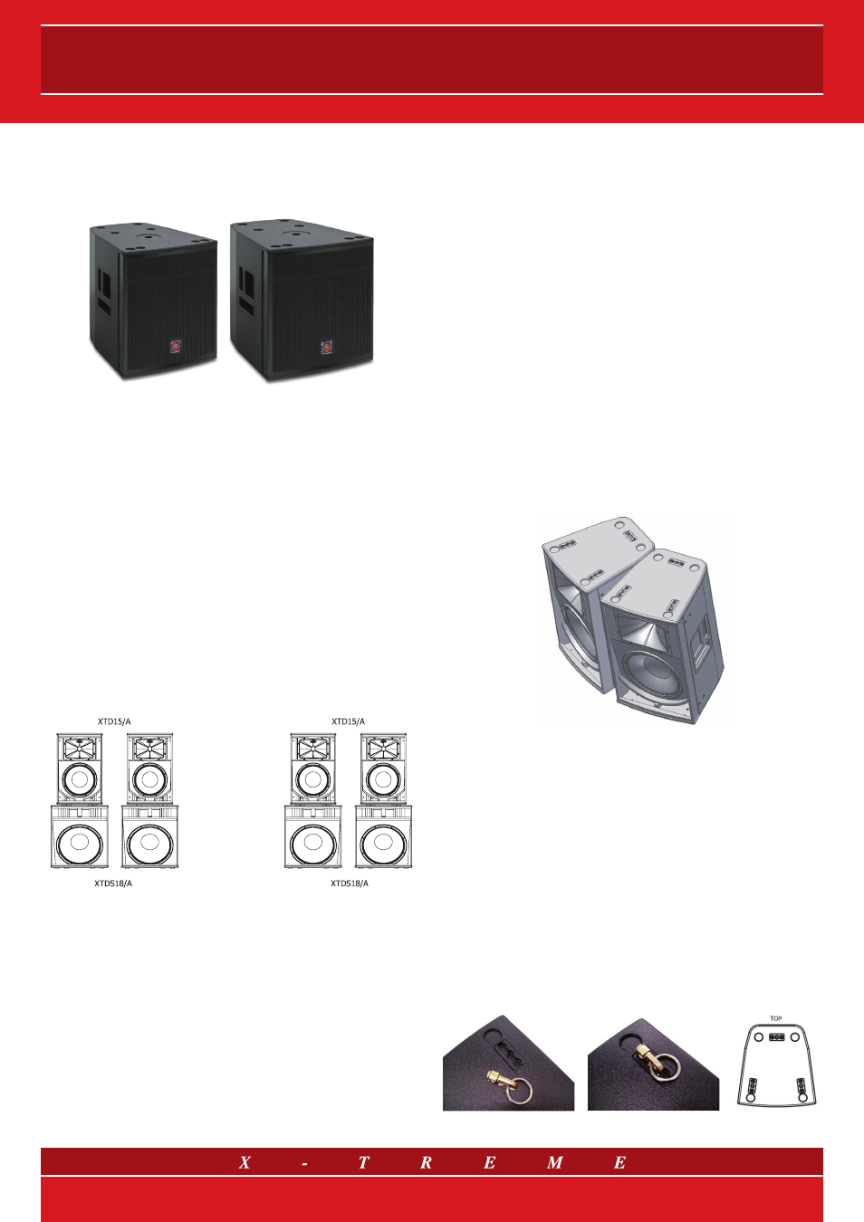
The
XTDS15 and XTDS18 subwoofers and their corresponding ampli-
fied versions both contain a woofer with a 15” Neodymium magnet at
1000 W (AES) for the XTDS15, and 18” 1200 W (AES) for the XTDS18.
The maximum SPL peaks are respectively 134 dB and 136 dB.
Fig. 8 XTDS15 and XTDS18 subwoofers
7. SYSTEM INSTALLATION
7.1 Ground stacked or suspended installation?
There are some arguments in favour of ground installation and some
which favour suspended; in both cases there are predominant rea-
sons for using one or the other, depending on practicality.
Excluding the possible logistical or visual problems of ground instal-
lation, which must be evaluated in each individual case, the positive
aspects of ground installation (stacking) are especially associated
with the main general coupling of low frequencies with the ground;
this makes the low part of the sound spectrum more efficient and, in
addition, it gains efficiency and response speed to the low transients.
This is also thanks to the fact that the speaker cabinets, which are
generally more physically constrained than the suspended ones, are
more stable and steady, and avoid turning part of the sound energy
into structure movement and losing it as a consequence. Another
point in favour of ground installation from the “spatial” and “psychoa-
coustic” perspectives, is the fact that the sound physically comes
from the points close to the stage, and therefore to the music scene.
Fig. 9 Stack installation of Deflector speakers
The choice of speaker suspension (flying), however, becomes com-
pulsory in all of those cases in which ground installation does not
provide the required sound coverage. When the medium-high fre-
quency transducers are not high enough compared to the listeners’
head-level, high frequencies will be poorer even at short distances,
due to the sound’s action of “friction” on the public (this being a
sound insulation element) and sound refraction phenomena, owing
to the vertical thermal gradient created by the public themselves.
Therefore, in general, ground installation is of little use to long dis-
tance coverage (the problem is reduced in the case of tilted slabs,
in which far away listeners find themselves at a slightly higher level
compared to those in the first few rows).
Additionally, for long distance coverage, guaranteeing sufficient SPL
(Sound Pressure Level) in the last few rows can lead to excessive SPL
in the first ones: in this case, suspension diminishes the SPL gap,
therefore distributing sound more evenly, as it reduces the differences
in distance from the system of close and long range listeners.
7.2 Angulations
Angulations must be managed carefully if more than one Deflector
line speaker is to be installed next to the stage. In fact, the high fre-
quencies emitted by speaker horns can cause negative interferences
with the others in certain points or spatial directions. One way of
checking this phenomenon is by tilting the speakers between them
to specific angles, which are calculated knowing the dispersion an-
gle of the sound beam emitted by the single horn; these angles are
used to determine both horizontal and vertical tilting. One particular
technique is to tilt the two speakers to an angle close to - or not too
much lower than - the horn’s dispersion half-angle: by doing this, if
the listener moves slightly away from the axis of the system made up
by the two coupled speakers, one of the two contributions becomes
more negligible than the other, which avoids harmful interference.
In the XTD12, XTD15 and XTD1015 models, an appropriate hori-
zontal inclination can be reached by making the countersinks of the
“short” parts of the cabinet sides fit together (as shown in figure 10).
Fig. 10 Installation with correct horizontal angulations
of a cluster of two XTD15 or similar models (XTD12 and XTD1015)
Conversely, by bringing the long sides of the speakers closer to-
gether, a narrower dispersion angle can be obtained, resulting in a
narrower coverage and a longer throw, but with a less harmonized
coverage in the nearby field. The choice, therefore, will be guided by
the shape and dimensions of the sound recording area.
7.3 Rigging
The
XTD12, XTD15 and XTD1015 models are equipped with state-
of-the-art flying track hooks, which permit immediate suspension via
steel cables, without having to screw extra elements into the cabinet
(eye bolts, articulated joints, pins, etc.). The flying track is present
in three positions, both on the upper and the lower surfaces of the
chassis, allowing the speaker-structure union (or speaker-flying bar)
as well as the speaker-speaker connection.
Fig. 11 Flying track ring hook (XT-FTH) and its positioning
5/12