Deflector line – X-Treme Audio Deflector Line User Manual
Page 7
8.4 Power cables
It is essential to use power cables with the correct section. If the
cables are too long they will cause significant impedance, which can
reduce the audio signal quality and alter the Dumping Factor of the
amplifier-speaker coupling. The following table shows the suggested
sections based on the length of power cables for various transducer
blockages.
Maximum length
CSA duct
4 ohm
8 ohm
1.0 mm
2
11 m
22 m
1.5 mm
2
17 m
34 m
2.0 mm
2
22 m
44 m
2.5 mm
2
29 m
58 m
4.0 mm
2
44 m
88 m
6.0 mm
2
66 m
132 m
9. GUIDELINES FOR USING ACTIVE SPEAKERS
All active versions of the Deflector line contain class D amplifiers and
DSP (Digital Signal Processor) with a 24 Bit word code and sampling
frequency of 96 kHz.
The
XTD88/A model has a built-in amplifier of 500 W (@8 Ohm) and
a DSP with 2 selectable presets, which can be chosen via a selector
switch on the back panel.
All of the top models,
XTD12/A, XTD15/A and XTD1015/A, are bi-am-
plified with an 800 + 800 W (@8 Ohm) class D amplifier and a DSP with
4 selectable presets, which can be set using 2 switches on the back
panel. The same electronic equipment is present in active subwoofers,
whose double amplifier is used in “bridged-mono” function for a single
amplification channel of 1600 W in total (@16 Ohm).
The DSP of every single module has been programmed in the fac-
tory, where crossover cuts, delays, equalizers and limiters, depend-
ing on the frequency, have been set up on each preset, which can
be selected by the user. All of this aims to create the best sound
with maximum SPL expression, with the complete assurance that
the amplifier or the speaker itself will not be damaged.
The back panel has an XLR type balanced input with direct link to
the output, Neutrik PowerCon input for power supply and related
loop output, volume control and the two switches for preset selec-
tion. One LED signals the power status, and another one indicates
the in signal presence (with a green light) and indicates the limita-
tion threshold (with a red light). In order to reach the maximum SPL
without compromising the dynamic quality of the signal, the red light
must come on intermittently and not continuously.
Fig. 12 Details of the rear panel of XTD12/A, XTD15/A and XTD1015/A
9.1 Technical information
XTD88/A
Input connectors
+4 dBu sens XLR, max input +10 dBu,
loop output
Front panel indicators
LED: power, signal, limit
Input impedance
5.5 kOhm unbal.,11kOhm bal.
DSP processing
24bit/96kHz; 2 selectable preset
Output power rating
500 W @8 Ohm
AC power connector
Neutrik PowerCon
AC voltage
115 or 230V ~ 40/60 Hz
XTD12/A, XTD15/A, XTD1015/A
Input connectors
+4 dBu sens XLR, max input +10 dBu,
loop output
Front panel indicators
LED: power, signal, limit
Input impedance
5.5 kOhm unbal.,11kOhm bal.
DSP processing
24bit/96kHz; 4 selectable preset
Output power rating (LF) 800 W @8 Ohm
Output power rating (HF) 800 W @8 Ohm
AC power connector
Neutrik PowerCon
AC voltage
115 or 230V ~ 40/60 Hz
XTDS15/A, XTDS18/A
Input connectors
+4 dBu sens XLR, max input +10 dBu,
loop output
Front panel indicators
LED: power, signal, limit
Input impedance
5.5 kOhm unbal.,11kOhm bal.
DSP processing
24bit/96kHz; 4 selectable preset
Output power rating
1600 W @16 Ohm
AC power connector
Neutrik PowerCon
AC voltage
115 or 230V ~ 40/60 Hz
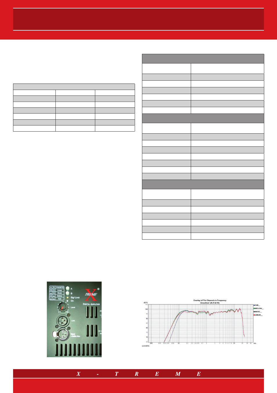
9.2 Presets
The two switches on the back of the
XTD12/A, XTD15/A and
XTD1015/A models make possible to select 4 presets: “linear”,
“
music”, “mellow”, and “sub”. The first three correspond to dif-
ferent equalizations, which can prove to be more suitable for repro-
ducing sound support or amplifying “live” sources. The “sub” preset
corresponds to “music” equalization, with a more selective high pass
cut, suitable for coupling with the pertinent Deflector subwoofer.
To provide an example, the figure shows the frequency responses
1
of
the four XTD15/A speaker presets.
Fig. 13 XTD15/A satellite presets
1
measured on the ground with reflective floor and microphone along the axis of 2 m
in virtually anechoic conditions (measurement of impulse response and separation of
reflections, the first obstacle at 4 m). Input signal – 20 dBu.
7/12