User’s manual – X-Treme Audio MISI User Manual
Page 10
12. Stacking instructions
The
stacked system has been designed for a maximum of 12
elements.
In this type of installations, the exact limits of vertical dispersion of
X-Treme array systems don’t leave any small error margin. Of course,
the FOH engineer should know if the audience will be standing or
sitting, but in any case, the lowest part of the array will always be
higher than the head of the first rows of the listening area.
If the array bottom is placed far down, the received SPL level in first
rows could be too high and the public standing in front of the system
could act as an acoustic barrier for the next rows. Ideally, the array
bottom should be located slightly above the audience (at least 2
metre high) and the volume of the lowest speaker should be set at
a suitable level.
Note: in the broad pass-band applications, a vertical stack of 4 sub-
woofers provides a solid base if it is 2 metre high from the floor
surface.
13. Suspension guidelines
As far as the anchoring points are concerned, the
flying system
has been designed for not more than
12 elements.
Pay special attention to the height at which the system is installed.
In several cases, in fact, it is easier to optimize the area coverage at
a specific height rather than another. In order to manage and carry
out a complex operation such as the installation of curved arrays
in a short time and safely, the X-Treme engineers have developed
a dedicated
software (XTI – see later), which allows calculation
of the
α angle of the vertical orientation. Note that the orientation
should not be performed by considering only the coverage area on
the axis, but also the geometry of the listening area outside the axis,
in particular from 45° to 60°. It is also possible to sound reinforce
places in which the two sections of the listening area have a differ-
ent shape. In this case, coverage of the areas close to the borderline
should be carefully determined and the array must be oriented dif-
ferently in the two sections.
13.1 X-Treme Installer (XTI)
It is a “custom-made” software system designed and developed
to favour a correct installation of the vertical line arrays (VLA) and
of X-Treme conventional loudspeaker systems. Starting from geo-
metric orientation, the software system calculates the sound field
through an algorithm based on the acoustic wave amplitude and
phase, according to the information available to the system. The
operator can set a few installation parameters, such as, for ex-
ample, the VLA position and the geometric variables associated
with the audience. Through simulation he can also control the
start-up and switching off of the VLA and the elemen ts making
up the clusters, thus guaranteeing broad and effective control of
the simulated sound field. Besides the VLAs, the softwa re system
enables the addition of other electro-acoustic speakers, such as
subwoofers or double subwoofers, with the configuration chosen
by the operator. Therefore, the sound field simulation allows inclu-
sion of both VLAs and sub clusters, which can be conceived as
horizontal arrays or, more commonly, as planar arrays working at
low frequencies. It should be stressed that the essential purpose
of this acoustic software tool is to allow the operator to check
directly the effect of any change in the VLA
vertical orientation
angle (the
α angle, that is the angle associated with the highest
speaker), in the orientation angles between the various modules
(
splay angles) and in the other VLA installation parameters on the
acoustic coverage of the audience area.
13.2 Suspension instructions
The
STD-LSA, STD-MISI, STD-MLA bars (see fig. 13) construct-
ed from martensitic steel tubular elements are designed to support
big loads. Equipped with two flying points, they are made of a rein-
forced central bar which is also used for lifting. The bars have a set
of holes with a 2.6 cm diameter working as a collection point for the
steel or lifting chains. The chosen collection point will determine the
inclination angle of the whole array. The line passing through the
two anchoring points crosses the barycenter of the flying system to
guarantee an aligned and balanced suspension. The two anchor-
ing points can be hooked separately to different suspension mo-
tors in order to share the load between the two points and to allow
the whole array to be inclined within certain limits. Alternatively, a
single motor and a single suspension point can be used while mak-
ing sure that a correct array inclination is achieved.
fig. 13
The new flying system without external hardware simplifies the in-
stallation procedure so much that it can be carried out by just one
person. No extra hardware must be hooked to the speaker system
and the system dimensions are such that transport becomes easy.
13.3 “Straight to the… Angle!”
The
XT-ANGLE is an electrical-mechanical device equipped with a
motorized linear actuator for remote adjustment of the vertical tilt-
ing of X-Treme arrays. The flying bar contains a worm screw which,
when set to rotate by the motor, allows the lengthways movement
of the coupling block and therefore the tilting of the flying bar (de-
pending on the weight distribution of the array). This system, which
is patent pending, offers unprecedented possibilities to professional
riggers (that have never been seen before).
In actual fact, it allows:
a) the array to be lifted without having to decide the anchoring point
beforehand;
b) more precise angles to be set, compared with those offered by
the anchoring hole of a traditional rod;
c) the system to be adjusted after mounting, without ever having to
bring it back down to the ground.
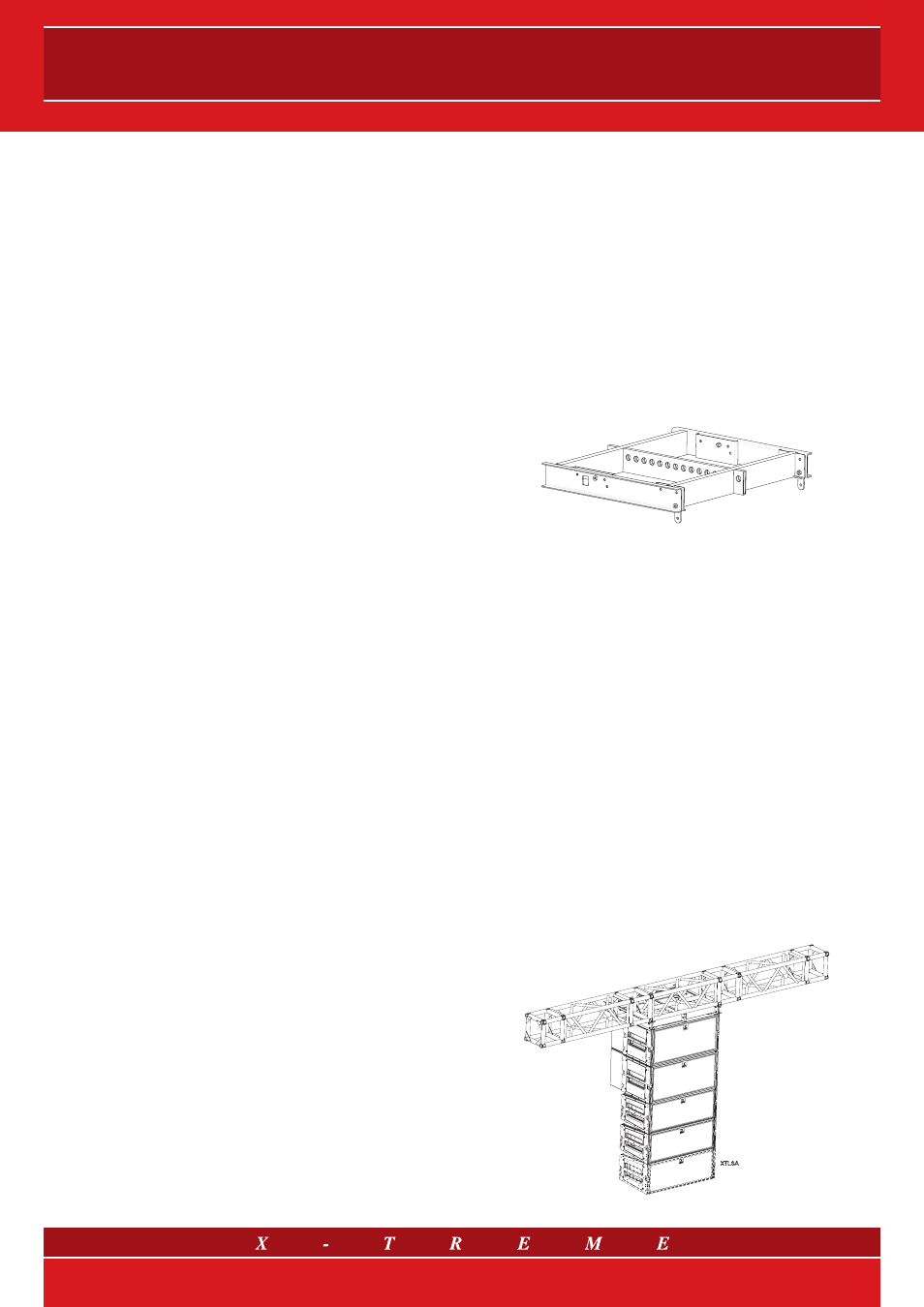
13.4 LSA: flying and lifting
XTLSAS
XTLSAS
XTLSA
XTLSA
fig. 14
10/21