Mounting location, About the high-performance fairing, Anti-fouling paint – Airmar B122—Long-Stem User Manual
Page 2: Hull types
2
Mounting Location
CAUTION: Do not mount near water intake or discharge
openings, or behind strakes, fittings, or hull irregularities that will
disturb the water flow.
CAUTION: Never mount the speed sensor directly ahead of a
depth transducer, since turbulence generated by the
paddlewheel’s rotation will adversely effect the depth transducer’s
performance, especially at high speeds. Mount side-by-side.
• The water flowing under the hull must be smooth with a
minimum of bubbles and turbulence (especially at high speeds).
• The sensor must be continuously immersed in water.
• The transducer beam must be unobstructed by the keel or
propeller shaft(s).
• Choose a location away from interference caused by power and
radiation sources such as: the propeller(s) and shaft(s), other
machinery, other echosounders, and other cables. The lower
the noise level, the higher the echosounder gain setting that
can be used.
• If the sensor will be installed without a fairing, choose a location
with a minimal deadrise angle, less than 10°, so the transducer
beam will be aimed at the bottom.
• Choose an accessible spot inside the vessel with adequate
headroom for the height of the housing, tightening the nuts, and
removing insert. Allow a minimum of 200mm (7-3/4") above the
top of the housing.
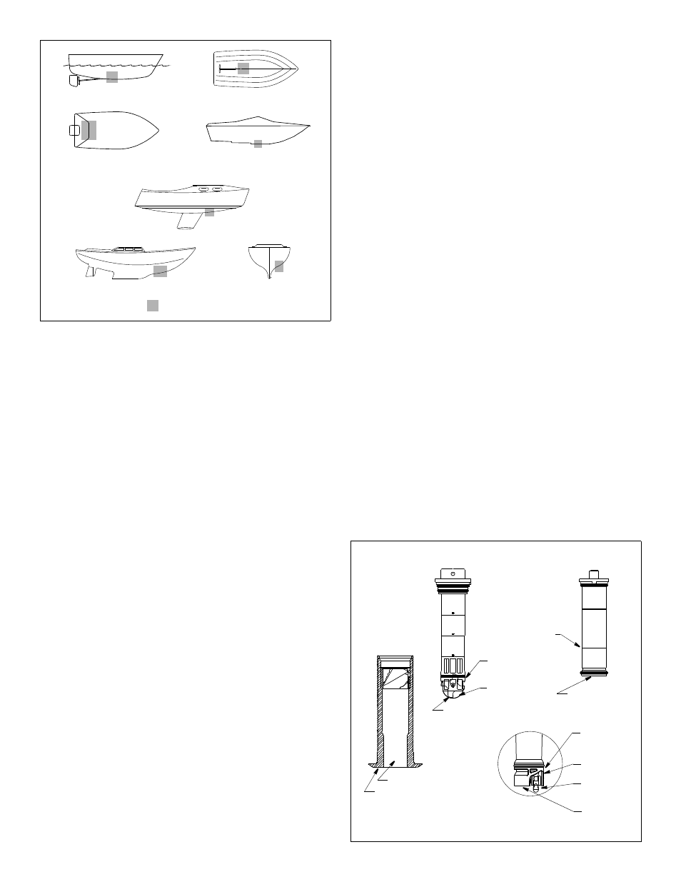
Hull Types
(see Figure 1)
• Displacement hull powerboat—Locate amidships near the
centerline. The starboard side of the hull where the propeller
blades are moving downward is preferred.
• Planing hull powerboat—Mount well aft, on or near the
centerline, and well inboard of the first set of lifting strakes to
ensure that the sensor will be in contact with the water at high
speeds. The starboard side of the hull where the propeller
blades are moving downward is preferred.
Outboard and I/O—Mount just forward of the engine(s).
Inboard—Mount well ahead of the propeller(s) and shaft(s).
Stepped hull—Mount just ahead of the first step.
Boat capable of speeds above 25kn (29MPH)—Review the
installation location and operating results of similar boats before
proceeding.
• Fin keel sailboat—Mount on or near the centerline and forward
of the fin keel 300–600mm (1–2').
• Full keel sailboat—Locate amidships and away from the keel
at the point of minimum deadrise angle.
About the High-Performance Fairing
Nearly all vessels have some deadrise angle at the mounting
location. If the sensor is mounted directly to the hull, the transducer
beam will be tilted to the side at the same angle as the deadrise. A
fairing is strongly recommended if the deadrise angle exceeds 10
°.
• Orients the transducer beam straight down by mounting the
sensor parallel to the water surface (see Figure 3).
• Mounts the sensor deeper in the water for clean flow under the
transducer face.
• Long streamlined shape directs the water around the sensor to
minimize drag.
Anti-fouling Paint
Marine growth can accumulate rapidly on the sensor’s surface
reducing performance in weeks. Surfaces exposed to salt water
must be coated with anti-fouling paint. Use water-based anti-
fouling paint only. Never use ketone-based paint, since ketones
can attack plastics possibly damage the sensor.
It is easier to apply antifouling paint before installation, but allow
sufficient drying time. Reapply paint every 6 months or at the
beginning of each boating season. Paint the following surfaces
(see Figure 2 ):
• Exterior flange of housing
• Bore of housing up 30mm (1-1/4")
• Insert and Blanking Plug:
- B122, Blanking Plug—Outside wall below lower joint
Exposed end
- DST800L, ST700—Outside wall below lowest O-ring
Any exposed end
Paddlewheel
Paddlewheel cavity
Figure 2. Anti-fouling paint
outside wall
paddlewheel
paddlewheel
exterior flange
bore up 30mm (1-1/4")
below
Copyright © 2001 - 2011 Airmar Technology Corp.
cavity
outside wall
paddlewheel
paddlewheel
O-ring
below lower
cavity
exposed end
(ST700 shown)
insert detail
planing hulls
Figure 1.
full keel sailboats
large displacement hulls
small displacement hulls
fin keel sailboats
Best location for sensor
Copyright © 2006 - 2011 Airmar Technology Corp
stepped hull
outboard and I/O
housing
insert
insert
outside wall
below joint
exposed end
ST700
lowest O-ring
B122/Blanking Plug
DST800L