No connector on display end: wiring – Airmar G2183 GPS User Manual
Page 13
13
No Connector on Display End: Wiring
If your sensor cable does NOT have a connector on the display end, it must be
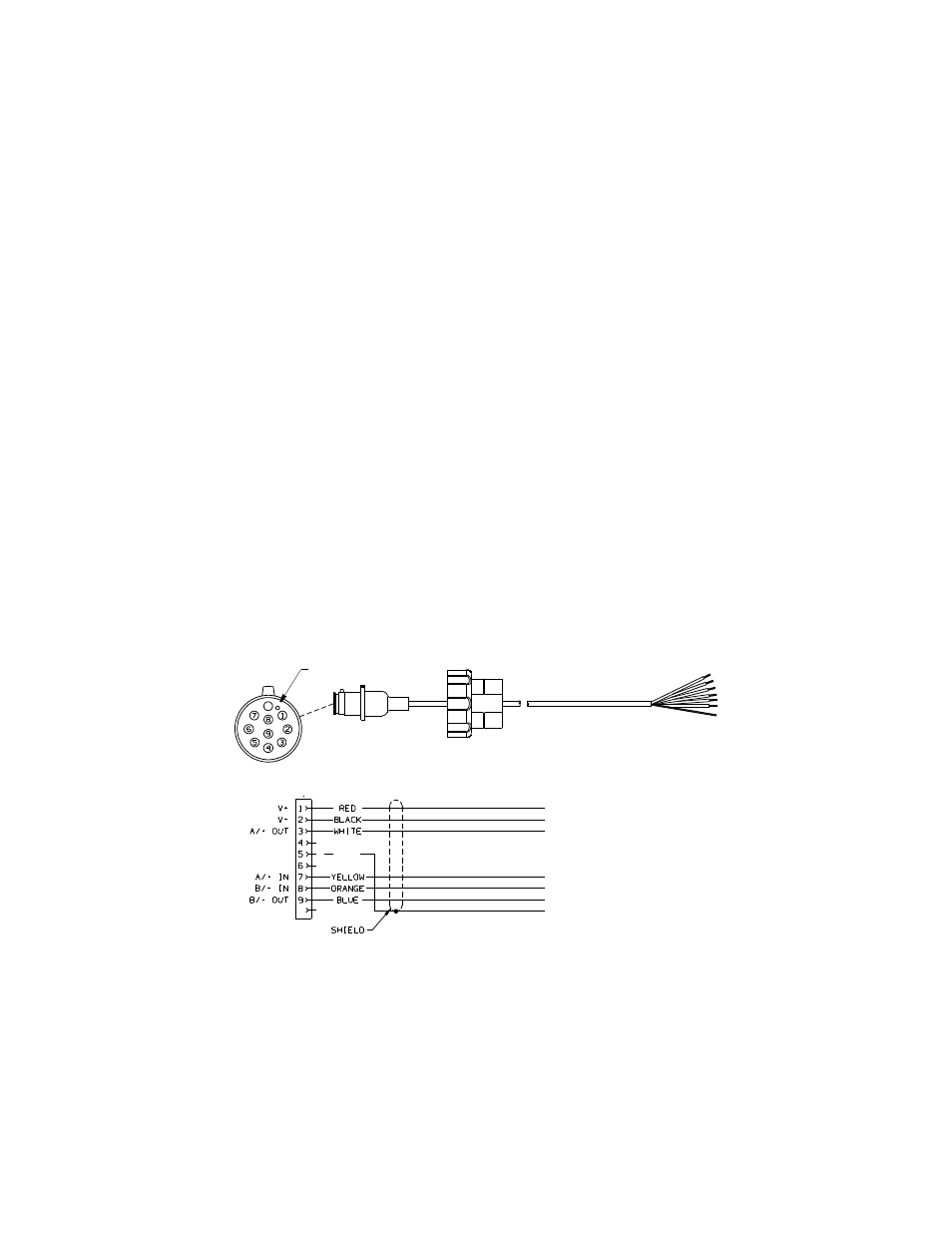
hard wired. Referring to the owner’s manual that came with your display, connect
the colored wires as show in Figure 4.
CAUTION: Your sensor has either an RS422 or RS232 interface. You must follow
the wiring diagram in Figure 4 that matches your sensor. If it is wired for the wrong
interface, it will not transmit and receive data properly.
NOTE: If your display does NOT have NMEA 0183 output connections, the yellow
and orange wires are not needed. Apply heat-shrink tubing to each unused wire.
(Alternatively, the yellow and orange wires can be connected to an external sensor.)
NOTE: The display power may be wired directly to the sensor cable, or it may be
wired separately.
1. Allowing an extra 25 cm (10") for wiring ease, cut the cable to length.
2. Strip 60mm (2-1/2") of the outer jacket and foil shielding from the cut end of the
cable (see Figure 4).
3. Strip 10 mm (3/8") of conductor insulation from the end of each colored wire.
4. Protect the cable’s foil shielding from causing a short by using heat-shrink tubing
around the jacket where the wires emerge from the cable. The tubing must
overlap the wires a minimum of 6mm (1/4"). Shrink the tubing using a heat gun.
5. Being sure the power supply is OFF, connect the wires to the display.
6. Fasten the cable in place.
7. Your installation is complete. To begin receiving data, refer to the owner’s
manual that came with your display.
Figure 4. NMEA 0183 sensor cable
sensor
10
connector
locator
Copyright © 2007 - 2014 Airmar Technology Corp.
BARE
x
10
RS422
RS232
V+
V-
TX OUT
RX IN
NO CONNECTION
NO CONNECTION
SHIELD
V+
V-
A /+ OUT
A/+ IN
B/- IN
B/- OUT
SHIELD
or
optional
optional