About fairings, Installation, Boat types (see figure 1) – Airmar B66VL User Manual
Page 2: Headroom, Airmar polymer fairing, Hole drilling
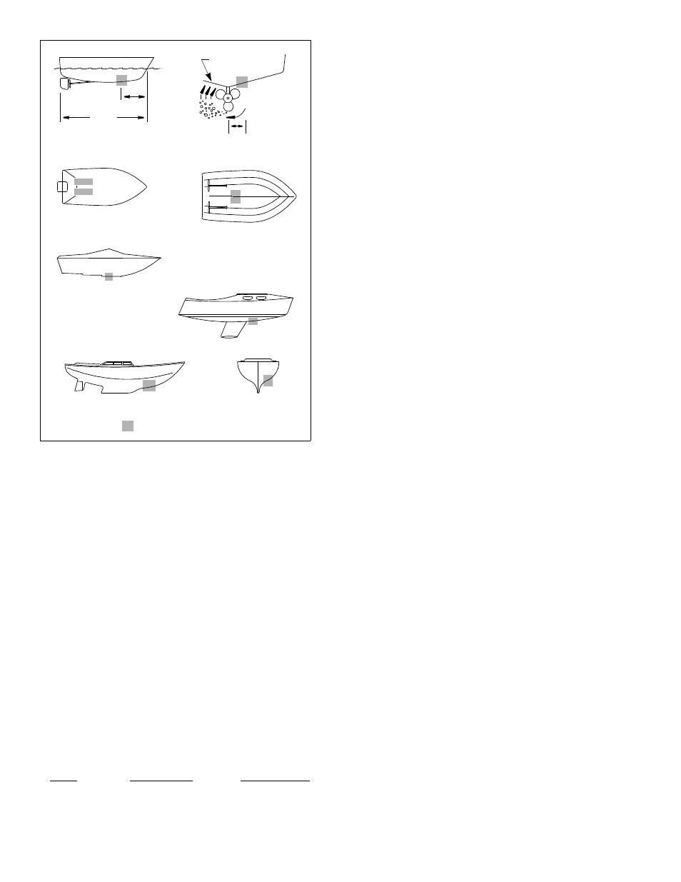
Boat Types (see Figure 1)
• Displacement hull powerboat—Locate 1/3 aft LWL and
150–300mm (6–12") off the centerline on the side of the
hull where the propeller is moving downward.
• Planing hull powerboat—Mount well aft near the centerline
and well inboard of the first set of lifting strakes to insure that
it is in contact with the water at high speeds. Mount on the
side of the hull where the propeller is moving downward.
Outboard and I/O—Mount forward and to the side of the
engine(s).
Inboard—Mount well ahead of the propeller(s) and shaft(s).
Step-hull—Mount just ahead of the first step.
Boats capable of speeds above 25kn (29MPH)—Review
multisensor location and operating results of similar boats
before proceeding.
• Fin keel sailboats—Mount to the side of the centerline
and forward of the fin keel 300–600mm (1–2').
• Full keel sailboats—Locate amidships and away from the
keel at the point of minimum deadrise angle.
Headroom
Allow adequate headroom inside the vessel for the height of
the housing, tightening the nuts and removing the insert.
Model
Min. no fairing
Min. with fairing
B744V
—
255mm (10")
B744VL
—
381mm (15")
B66V
270mm (10
5
⁄
8
")
255mm (10")
B66VL
394mm (15
1
⁄
2
")
381mm (15")
About Fairings
Nearly all vessels have some deadrise angle at the mounting location. If
the multisensor is mounted directly to the hull, the sound beam will be
tilted off the vertical at the same angle as the deadrise. A fairing is
strongly recommended if the deadrise angle exceeds 10
°(see Figure 2).
• Increases the sealing surface around the drilled hole to prevent
water from leaking into the hull.
• Orients the sound beam straight down by mounting the multisensor
parallel to the water surface
• Minimizes aerated water flowing over the transducer’s face by
mounting it deeper in the water
• High-Performance Fairing has a long streamlined shape for
excellent performance above 15 knots (see Replacement Parts on
page 6).
Airmar Polymer Fairing
Made of a high impact polymer with an integrated cutting guide, an
Airmar fairing is safer and easier to cut with a band saw and shape
with hand tools than custom fairings. It can be shaped to
accommodate a deadrise angle of up to 25
°. (For fairing part numbers,
see “Replacement Parts” on page 6.)
A backing block is used inside the hull to provide a level surface for the
hull nut to seat against (see Figure 2). It is fabricated matching the
interior deadrise angle of the boat. After cutting an Airmar fairing, use
the remaining section with the cutting guide as the backing block.
Installation
(for Standard Fairing Only)
WARNING: B744V, B744VL with a High-Performance Fairing must
be installed following the supplemental instructions that came with
your High-Performance Fairing. The High-Performance Fairing
requires an anti-rotation bolt. Failure to install the anti-rotation bolt may
result in the fairing rotating while the boat is underway. The effect may
be violent movement and loss of steering. This could result in serious
injury or death to passengers and/or damage to the boat or other
property.
WARNING: B744V and B744VL
must be installed with a fairing
(Standard or High-Performance). If it is installed without a
fairing, there is insufficient surface area to seal the sensor to
the hull. Water may leak into the hull causing damage to the
boat or possibly sinking.
CORED FIBERGLASS HULL—Follow separate instructions on page 4.
Hole Drilling
Warning: Always wear safety goggles and a dust mask.
1. Drill a 3mm or 1/8" pilot hole perpendicular to the waterline from
inside the hull (see Figure 3). If there is a rib, strut, or other hull
irregularity near the selected mounting location, drill from the outside.
If the pilot hole is drilled in the wrong location, drill a second hole in a
better location. Apply masking tape to the outside of the hull over the
incorrect hole and fill it with epoxy.
2. Using the 51mm or 2" hole saw, cut a hole from outside the hull. Be
sure to hold the drill plumb, so the hole will be perpendicular to the
water surface.
3. Sand and clean the area around the hole, inside and outside, to
ensure that the sealant will adhere properly to the hull. If there is any
petroleum residue inside the hull, remove it with either mild household
detergent or a weak solvent (alcohol) before sanding.
2
inboard
Figure 1.
pressure waves
1/3 aft
full keel sailboat
displacement hull
(6–12")
fin keel sailboat
150–300mm
LWL
Best location for the multisensor
(Load Waterline Length)
step-hull
outboard and I/O
planing hulls
AIRMAR
®