Check for leaks, Antifouling paint, Operation, maintenance , repair, & parts – Airmar B66VL User Manual
Page 5: How the valve works, Blanking plug
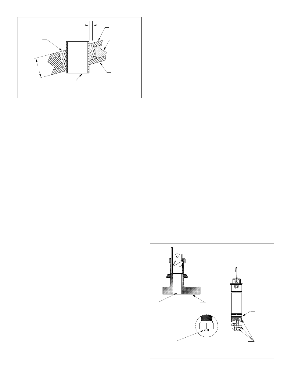
2. Using the 51mm or 2" hole saw, cut a hole from outside the hull
through the outer skin only. Be sure to hold the drill plumb, so
the hole will be perpendicular to the water surface.
3. The optimal interior hole diameter is affected by the hull’s
thickness and deadrise angle. It must be large enough in
diameter to allow the core to be completely sealed.Using the
60mm or 2-3/8" hole saw, cut through the inner skin and most
of the core from inside the hull keeping the drill perpendicular to
the hull. The core material can be very soft. Apply only light
pressure to the hole saw after cutting through the inner skin to
avoid accidentally cutting the outer skin.
4. Remove the plug of core material so the inside of the outer skin
and inner core of the hull is fully exposed. Sand and clean the
inner skin, core, and the outer skin around the hole.
Caution: Completely seal the hull to prevent water seepage
into the core.
5. Coat a hollow or solid cylinder of the correct diameter with wax
and tape it in place. Fill the gap between the cylinder and hull
with casting epoxy. After the epoxy has set, remove the
cylinder.
6. Sand and clean the area around the hole, inside and outside, to
ensure that the sealant will adhere properly to the hull. If there
is any petroleum residue inside the hull, remove it with either
mild household detergent or a weak solvent such as alcohol
before sanding.
7. Proceed with “Bedding the Housing” and “Installing the Housing”.
Check for Leaks
Warning: Never install a thru-hull multisensor and leave the boat
in the water unchecked for several days.
When the boat is placed in the water, immediately check the
thru-hull multisensor for leaks. Note that very small leaks may not
be readily observed. It is best not to leave the boat in the water for
more than 3 hours before checking it again. If there is a small
leak, there may be considerable bilge water accumulation after 24
hours. If a leak is observed, repeat “Bedding the Housing” and
“Installing the Housing” immediately.
Antifouling Paint
Marine growth can accumulate rapidly on the multisensor’s
surface reducing performance within weeks. Surfaces exposed to
salt water must be coated with antifouling paint. Use water-based
antifouling paint only. Never use ketone-based paint since
ketones can attack many plastics possibly damaging the
transducer. Reapply paint every 6 months or at the beginning of
each boating season.
Paint the following surfaces (see Figure 9):
• Exposed areas of the housing including the acoustic window
• Bore of the housing up 30mm (1-1/4")
• Outside wall below lower O-ring of paddlewheel insert
• Paddlewheel cavity
• Paddlewheel
• Blanking plug below lower O-ring including exposed end
Operation, Maintenance, Repair, & Parts
How the Valve Works
The multisensor incorporates a self-closing valve which minimizes
the flow of water into the vessel when the paddlewheel insert is
removed. The curved flap valve in the valve assembly is activated
by both a spring and water pressure. The flap valve is pushed
upward to block the opening, so there is no plume of water into
the boat (see Figure 6).
WARNING: THE VALVE IS NOT A WATERTIGHT SEAL.
Always use the paddlewheel insert or blanking plug secured with
the retaining pin, safety ring, and safety wire for a watertight seal.
Blanking Plug
To protect the paddlewheel, use the blanking plug when:
• The boat will be moored in salt water for more than a week.
• The boat will be removed from the water.
• Aquatic growth buildup on the paddlewheel is suspected due to
inaccurate readings from the instrument.
WARNING: The O-rings must be intact and well lubricated for
a watertight seal.
1. Inspect the O-rings on the blanking plug and lubricate them with
silicone lubricant or petroleum jelly (Vaseline®) (see Figure 6).
2. Remove the safety wire from the pull ring and cap nut. Remove
the safety ring and pull out the retaining pin (see Figure 7).
Do not remove the cap nut.
3. Grasp the pull ring and remove the paddlewheel insert with a
slow pulling motion.
Note: In the unlikely event that the paddlewheel insert cannot
be removed, see “Servicing the Valve Assembly”.
4. With the arrow on the top pointing forward, slide the blanking
plug into the housing until it is fully seated. Secure it with the
retaining pin, safety ring, and safety wire (see Figure 6).
Figure 9. Antifouling paint
(B744V shown)
Paint outside wall below the lower O-ring
including exposed end, paddlewheel cavity and paddlewheel
Paint exposed housing
lower
O-ring
and bore up 30mm (1-1/4")
paddlewheel
insert
housing
detail
hull’s outer skin to
hull
outer skin
solid or hollow
cylinder
pour in
casting
epoxy
core
inner skin
Figure 8. Preparing a cored fiberglass hull
Dimension equal to
the thickness of the
ensure adequate
clearance
5
AIRMAR
®
AIRMAR
®