Airmar 2-3 kW—R99 User Manual
Installation instructions owner’s guide, External-mount, 2, 3kw depth transducer
17
-3
35
-0
1 re
v.
1
0
01
/09
/14
External-Mount, 2
-
3kW
Depth Transducer
with Temperature Sensor
Models: R99, R109LH, R109LM, R109LH-W, R209, R309,
R509LH, R509LM, R509LH-W, R609LH, R609LM
U.S. Patent No. 7,369,45; 8,582,393. UK Patent No. 2 414 077
I
MPORTANT: Please read the instructions completely
before proceeding with the installation. These instructions
supersede any other instructions in your instrument manual
if they differ.
Applications
• Recommended for all hull materials
• Not recommended for hulls less than 9m (30') long
• Not recommended for stepped hulls. Mount an in-hull transducer
• Accommodates a deadrise angle up to 22
°
Unpacking & Pretest
Remove and discard the packing hardware (rod and 2 nuts) (see
Figure 1). Connect the temperature function to the instrument and
check for the approximate air temperature. If there is no reading
or it is inaccurate, check the connections and test again. If there is
still a problem, return the product to your place of purchase.
Tools & Materials
Safety goggles
Dust mask
Angle finder
Band saw (blade must be very sharp)
Rasp or power tool
Electric drill
Drill bits:
pilot hole
3mm or 1/8"
fiberglass, wood, or steel hull 14mm or 9/16"
aluminum hull
15mm or 9/16"
Permanent marker
Mild household detergent or weak solvent (such as alcohol)
Sandpaper
File (installation in a metal hull)
Marine sealant (suitable for below waterline)
Wrenches
Torque wrench
Grommet(s) (some installations)
Cable ties
Water-based anti-fouling paint (mandatory in salt water)
Record the information found on the cable tag for future reference.
Part No.:_________________Date___________Frequency________kHz
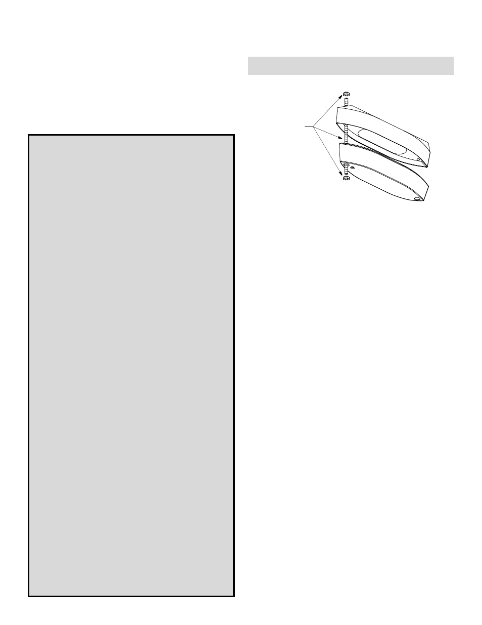
transducer
fairing
Remove
and discard
the packing
hardware.
Figure 1. Packing hardware
Copyright © 2007 Airmar Technology Corp.
Follow the precautions below for optimal
product performance and to reduce the risk of
property damage, personal injury, and/or death.
WARNING: Boats capable of speeds above 25kn
(29MPH)—You must follow these instructions for a
safe installation. For boats exceeding 35 kn. (40MPH)
or when the instructions cannot be met, mount an in-
hull transducer. At high speeds, the fairing and/or
transducer may break away from the boat.
WARNING: A stuffing tube is required. The stuffing tube
seals the hull forming a water-tight conduit for the cable.
WARNING: Always wear safety goggles and a dust
mask when installing.
WARNING: The fairing must be installed parallel to the
keel to ensure proper boat handling and water flow
under the transducer.
WARNING: Immediately check for leaks when the boat
is placed in the water. Do not leave the boat in the water
unchecked for more than three hours. Even a small leak
may allow considerable water to accumulate.
WARNING: Fiberglass hull—The transducer and stuffing
tube must be installed in solid fiberglass, not in coring
CAUTION: Aluminum hull—The stainless steel
hardware must be isolated from an aluminum hull to
prevent electrolytic corrosion.
CAUTION: Steel hull—Follow generally accepted
installation practices.
CAUTION: Never install a metal fitting on a vessel with
a positive ground system.
CAUTION: External mount only. The transducer will
overheat if it is mounted in a hull pocket.
CAUTION: Never pull, carry, or hold the transducer by
its cable. This may sever internal connections.
CAUTION: Never strike the transducer.
CAUTION: Tighten the nylon locking nuts with a torque
wrench using a force not exceeding 27N-m (20ft.-lb.).
Do not over tighten. It may crack the transducer and/or
crush the fairing.
CAUTION: Never use solvents. Cleaner, fuel, sealant,
paint, and other products may contain solvents that can
damage plastic parts, especially the transducer’s face.
INSTALLATION INSTRUCTIONS
OWNER’S GUIDE &