Mounting location, Stuffing tube, Fairing: cutting, bedding & installing – Airmar 2-3 kW—R99 User Manual
Page 2: Guidelines, Hull types, Cutting the fairing
2
Figure 6. Fairing
Figure 5. Fairing
NOTE: After the fairing is cut,
the section with the cutting guide
becomes the backing block.
20mm
(3/4")
cutting
guide
cavity for
22° max
cutting
guide
min.
stuffing
tube
bottom view
aft view
Copyright © 2007 - 2011 Airmar Technology Corp.
Copyright © 2005 Airmar Technology Corp.
Figure 4. Cutting the fairing
cutting
guide
band saw
table
deadrise
angle
fence
Copyright © 2005 Airmar Technology Corp.
location
of stuffing
tube
Bow >
Mounting Location
Guidelines
CAUTION: Do not mount in line with or near water intake or
discharge openings or behind strakes, fittings, or hull irregularities
that will disturb the water flow.
CAUTION: Do not mount the sensor where the boat may be
supported during trailering, launching, hauling, or storage to avoid
damaging the transducer’s face.
• The water flowing under the hull must be smooth with a
minimum of bubbles and turbulence (especially at high speeds).
• The transducer must be continuously immersed in water.
• The transducer beam must be unobstructed by the keel or
propeller shaft(s).
• Choose a location away from interference caused by power and
radiation sources such as: the propeller(s) and shaft(s), other
machinery, other echosounders, and other cables. The lower
the noise level, the higher the echosounder gain setting that
can be used.
• Choose a location with a minimal deadrise angle, not to
exceed 22
°
.
• Choose an accessible spot inside the vessel with adequate space
for the height of the stuffing tube and tightening the nuts.
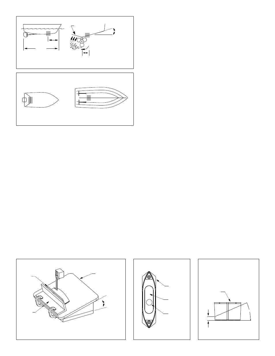
Hull Types
• Displacement hull powerboat—Locate about 1/3 of the way
along the LWL and 200–600mm (8–24") off the centerline (see
Figure 2). The starboard side of the hull where the propeller
blades are moving downward is preferred.
• Planing hull powerboat— (see Figure 3)
• Mount within the aft 1/3 of the hull, as far back as possible.
Outboard and I/O—Mount just forward of the engine(s).
Inboard—Mount ahead of the propeller(s) and shaft(s).
• Mount on or as close to the centerline as possible, and well
inboard of the first set of lifting strakes to ensure that the
transducer is in contact with the water at high speeds.
• Mounting on the starboard side of the hull where the
propeller blades are moving downward is preferred.
Stuffing Tube
After determining the best mounting location for the transducer,
install the stuffing tube. Follow the installation instructions
packaged with the stuffing tube.
Fairing: Cutting, Bedding & Installing
Cutting the Fairing
CAUTION: Shape the fairing to the hull as precisely as possible. If
there are gaps between the fairing and the hull near the ends, cut
a new fairing. Over tightening the rods to minimize gaps may
crack the transducer and/or crush the fairing.
1. Measure the deadrise angle of the hull at the stuffing tube using
an angle finder or digital level (see Figure 2).
2. Tilt the band saw table to the measured angle and secure the
cutting fence (see Figure 4). Do not exceed 22
°
.
3. Place the fairing on the table so the cutting guide rests against
the fence (see Figures 4 and 5). Note the fairing is symmetrical.
4. Adjust the fence so the fairing will be cut in about two equal parts.
The section that will become the fairing must be a minimum of
20mm (3/4") at its thinnest dimension (see Figure 6).
5. Recheck steps 1 through 4; then cut the fairing.
6. Check the fit by placing the fairing against the hull. Be sure the
fairing is parallel to the centerline of the boat (keel), and the
stuffing tube is about 2/3 of the way back in the cavity (see
Figure 5). Hold the fairing on the ends and try to rock it back
and forth. Shape the fairing to the hull as precisely as possible
with a rasp or power tool until it no longer rocks.
deadrise
slope of hull
parallel to
Figure 2. Transducer location on displacement hull
pressure waves
1/3
(8 – 24")
200-600mm
LWL
(Load Waterline Length)
angle
waterline
Copyright © 2005 Airmar Technology Corp.
Figure 3. Transducer location on planing hull
inboard
outboard and I/O
Copyright © 2005, 2009 Airmar Technology Corp.
NOTE: Mount within the
aft 1/3 of the hull, as far
back as possible.