Connecting & testing, B. two-cable multisensor – Airmar B744V User Manual
Page 3
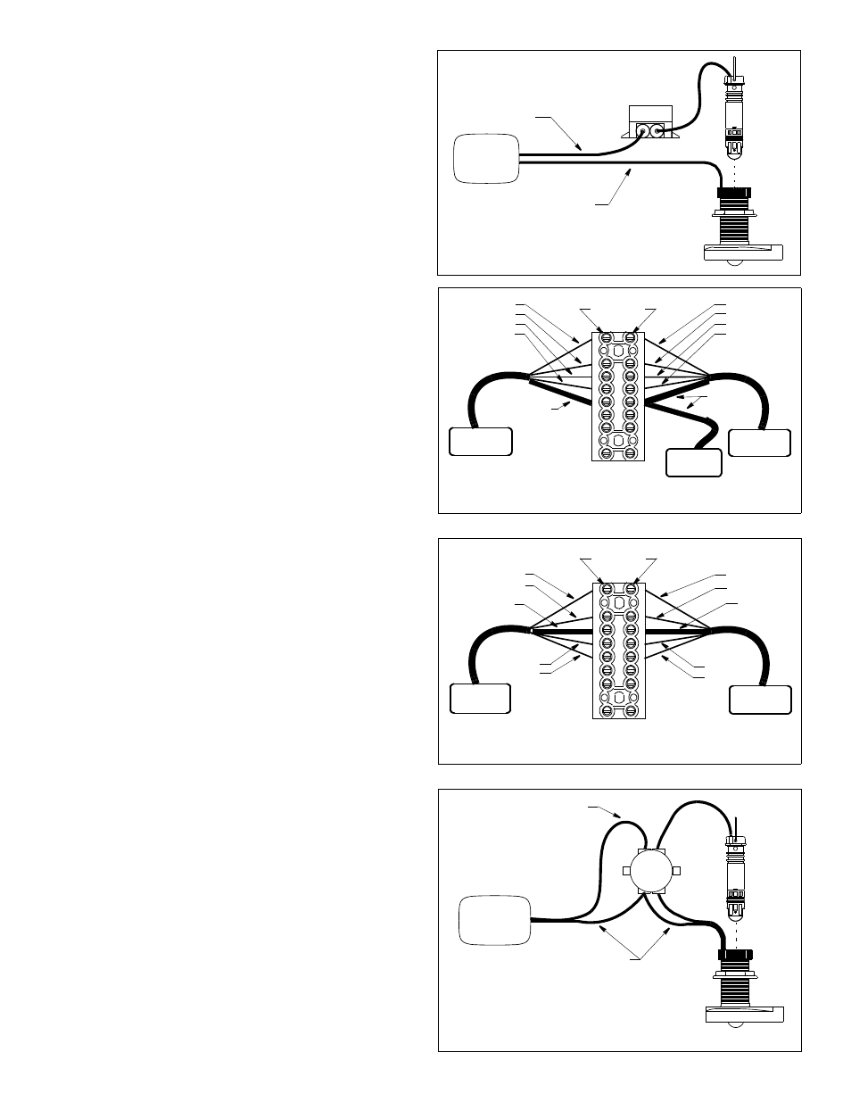
Figure 9. Splicing both halves of a zip-cable
echosounder
speed/temp half of zip-cable
(printed half)
(contains red, green, brown,
white, and bare wires)
depth-transducer
half of zip-cable
(contains blue, black,
orange, and bare wires)
A
B
C
3-5 3-5
5-7 5-7
D
E
insert
multisensor
Copyright © 2002, 2009 Airmar Technology Corp.
B. Two-cable Multisensor
CAUTION: Do not cut the depth-transducer cable.
CAUTION: Do not puncture unused grommets.
1. Disconnect the multisensor from the echosounder.
2. On the junction box, use a small Phillips screwdriver to
puncture the center of both 5-7 grommets only (see Figure 6).
3. Near the marked location for the junction box, cut the cable
leading to the speed/temp insert ONLY. Do not cut the depth
transducer cable.
4. Strip 6cm (2-1/2") of the outer jacket and foil shield from the
cable ends (see Figure 4).
5. Strip 13mm (1/2") of insulation from the end of each colored wire.
6. Bend the stripped wires of each cable back against its cable
jacket (see Figure 5). Apply alcohol to the cut end of each cable
jacket to ease sliding. (Do not use any other lubricant to ease
sliding. It will interfere with sealing the grommets.) Push about
20cm (8") of each cable through a grommet until all the wires
are inside the junction box (see Figure 6). Bend the wires back
to their original position (see Figure 5).
7. Slide a black sleeve over each bare wire and position it against
the cable jacket. For ease in holding the sleeves in place and
connecting to the terminals, fold the stripped ends of each wire
in half. Twist the ends and bend them 90
°
(see Figure 4).
Connecting & Testing
CAUTION: Make certain there are no bare wires, frayed strands,
or loose ends to cause shorting.
CAUTION: Zip-cable multisensor—If the depth-transducer half
of the cable (with the blue, black, orange, and bare wires) has
been cut, re-connect it FIRST before connecting the new speed/
temp insert (see Figure 11 on page 4).
1. Insert the stripped end of a colored wire from the echosounder
cable A into the first square opening in the side of the terminal
block (see Figure 7 or 8). Tighten the terminal screw until the
wire is held firmly. Connect each wire in turn including the bare
wire.
2. Connect each matching colored wire and bare wire from the
new speed/temp insert (cable C) to the corresponding terminal.
Zip-cable multisensor—Twist the bare wire from cable B and
the bare wire from cable C together. Connect the twisted pair of
bare wires to the terminal (see Figure 7). This shields the depth
transducer from acoustic noise.
3. Visually inspect all the wires. Make certain the sleeving
completely covers any bare wire(s). There should be no frayed
strands or loose ends to cause shorting. If any bare wire is
visible, shorten the stripped end and reconnect it to the terminal.
4. Connect the cable to the echosounder and turn it ON.
5. Check for the approximate air temperature.
6. Spin the new paddlewheel and look for a speed reading.
NOTE: If the new insert does not work properly, the wiring may
be incorrect. Return to step 1 and recheck your wiring.
3
Figure 6. Splicing a two-cable multisensor
Copyright © 2002, 2009 Airmar Technology Corp.
Figure 7. Connecting a zip-cable multisensor
red
green
bare wire
with black
terminals
sleeve
red
green
white
white
speed/temp
echosounder
multisensor
A
B
C
Copyright © 2002, 2009, 2010 Airmar Technology Corp.
brown
brown
bare wire
with black
sleeve
insert
Figure 8. Connecting a two-cable multisensor
red
white
terminals
red
white
bare wire
speed/temp
echosounder
A
C
brown
brown
green
with sleeve
green
Copyright © 2002, 2010 Airmar Technology Corp.
bare wire
with sleeve
insert
echosounder
depth
speed/temp
cable
cable
transducer
3-5
3-5
multisensor
insert