Airmar, Closing & mounting, Anti-fouling paint – Airmar B744V User Manual
Page 4: Installing the speed temperature insert, Parts
4
Closing & Mounting
1. Apply alcohol to each cable jacket inside the junction box to ease
sliding. Grasp each cable from outside the box and pull until only
25mm (1") of the cable jacket is left inside. This will invert the
grommets to seal the junction box.
2. Arrange the wires neatly inside the junction box.
3. Place the terminal block inside the junction box. Secure the
ends with the terminal block screws provided (see Figure 1).
4. Close the box using the red cap. Expel the excess air inside the
junction box by placing a thumb on the center of the red cap
and applying pressure for 30 seconds.
5. Screw the junction box to the selected mounting surface using
the two #6 x 1/2" (13mm) screws provided.
Anti-fouling Paint
Aquatic growth can accumulate rapidly on the speed/temp insert
reducing its performance within weeks. Surfaces exposed to salt
water must be coated with anti-fouling paint. Use water-based
anti-fouling paint only. Never use ketone based paint since
ketones can attack many types of plastic. Paint the following
surfaces:
• Exposed end of the insert
• Outside wall of the insert below the lower O-ring
• Paddlewheel cavity
• Paddlewheel
Installing the Speed Temperature Insert
WARNING: Different speed/temperature inserts are attached to
the multisensor in different ways. See your multisensor’s owner’s
guide for more details.
WARNING: O-ring must be intact and well lubricated to make a
watertight seal.
WARNING: Always attach the safety wire to prevent the insert
from backing out in the unlikely event that the cap nut and/or
insert nut fails or is screwed on incorrectly.
1. Check the O-rings on the new insert (replace if necessary) and
lubricate them with silicone lubricant or petroleum jelly.
2. Remove the failed speed/temperature insert from the housing.
If desired, save it for replacement parts. The paddlewheel and
shaft may be usable.
3. Slide the new insert into the valve assembly with the arrows on
the top pointing forward until it is fully seated.
• Insert nut—Use a twisting motion until the keys fit into the
notches. (The insert fits one way only.) Screw the insert nut
in place and hand-tighten only. Do not over tighten.
• Safety chain or Strap assembly—Reattach the safety
chain/strap assembly to the cable. Slide the retaining pin
through the holes and secure it with the safety ring(s).
4. Reattach the safety wire.
AIRMAR
®
TECHNOLOGY CORPORATION
35 Meadowbrook Drive, Milford, New Hampshire 03055-4613, USA
www.airmar.com
Copyright © 2002 - 2010 All rights reserved.
CAUTION: Reconnect the
depth transducer before
Copyright © 2002, 2010 Airmar Technology Corp.
connecting the new
speed/temp insert
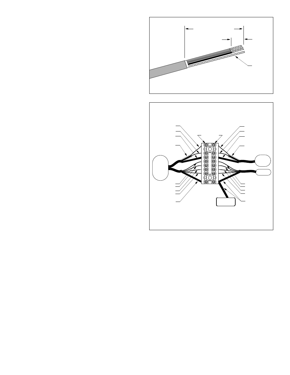
Figure 11. Reconnecting a depth transducer and
connecting new speed/temp insert
Figure 10. Preparing the cut ends of the
bare
Copyright © 2002, 2009 Airmar Technology Corp.
6cm (2 1/2")
remove outer jacket and foil shielding
13mm
(1/2")
remove
insulation
wire
black
bare wire with
red
green
white
black sleeve
terminals
shielded pair
bare wire with
black sleeve
with clear
black
bare wire with
red
green
white
black sleeve
shielded pair
bare wire with
black sleeve
with clear
sleeve
sleeve
blue
blue
depth
insert
A
D
E
C
multisensor
B
echosounder
speed/temp
multisensor
speed/temp
depth
brown
brown
depth-transducer half of a zip-cable
Parts
Obtain parts from your instrument manufacturer or marine dealer.
Gemeco
Tel: 803-693-0777
(USA)
Fax: 803-693-0477
email: [email protected]
Airmar EMEA
Tel: +33.(0)2.23.52.06.48
(Europe, Middle East, Africa) Fax: +33.(0)2.23.52.06.49
email: [email protected]