Mounting location, Testing the selected mounting location – Airmar 2-3 kW—R199 User Manual
Page 2
Mounting Location
About Fiberglass Hulls
Since the hull absorbs acoustic energy, transmitting through the
hull reduces the transducer’s performance. Fiberglass hulls are
often cored in places for added strength or to reduce weight. These
cored areas contain balsa wood or structural foam which are poor
sound conductors. Do not locate the transducer over coring.
Choose a Location
• Where the fiberglass is solid (no air bubbles are trapped in the
fiberglass resin) and where no coring, flotation material, or dead
air space is sandwiched between the inside skin and outer skin
of the hull.
• Where the hull below the transducer will be in contact with the
water at all times.
• Where the water flowing under the hull is smoothest with a min-
imum of bubbles and turbulence (especially at high speeds). Do
not mount the transducer near water intake or discharge open-
ings; or behind strakes, fittings, or hull irregularities.
• Where the transducer beam will not be blocked by the keel or
propeller shaft(s).
• Away from interference caused by power and radiation sources
such as: the propeller(s) and shaft(s), other machinery, other
echosounders, and other cables. The lower the noise level, the
higher the echosounder gain setting that can be used.
• Where the deadrise angle does not exceed either 12° on the
long side of the tank or 22° on the short side of the tank.
• Where there is space inside the vessel for the size of the tank
and removing the transducer.
• CHIRP transducer—Mount in a cool well-ventilated area away
from the engine to avoid overheating the liquid inside the tank.
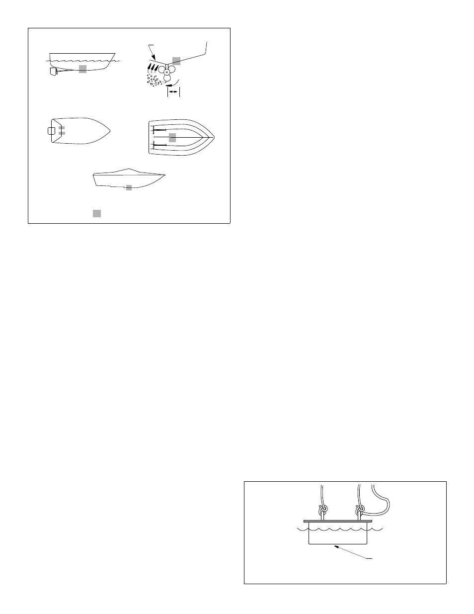
Boat Types
(see Figure 3)
• Displacement hull powerboats—Locate amidships near the
centerline. The starboard side of the hull where the propeller
blades are moving downward is preferred.
• Planing hull powerboats—Mount well aft, on or near the
centerline, and well inboard of the first set of lifting strakes to
ensure that the transducer will be in contact with the water at
high speeds. The starboard side of the hull where the propeller
blades are moving downward is preferred.
Outboard and I/O—Mount just forward of the engine(s).
Inboard—Mount well ahead of the propeller(s) and shaft(s).
Stepped hull—Mount just ahead of the first step.
Testing the Selected Mounting Location
Establishing a Performance Baseline
The results of this test are used as a basis of comparison to
determine the best in-hull location for the transducer.
1. Take the boat to the maximum depth in which you will be
operating the echosounder. If deep water is not available, find a
location with at least 30m (100').
2. Connect the transducer to the echosounder.
3. Tie a rope securely around the handles of the transducer (see
Figure 4). Lower it over the side of the boat until the active face
is fully submerged and parallel to the water surface.
4. Observe the echosounder’s performance and the depth reading.
Testing the Location
While the boat is at the same site (depth of water), test the
transducer inside the hull at the mounting location. Use one of the
test methods below:
A.If the transducer will be located near the stern and the boat
has a minimum deadrise angle—Clean away any build-up of
dirt and/or grease using detergent or a weak solvent such as
alcohol. Place the transducer against the hull and allow bilge
water to cover the surface where they touch (see Figure 5-A).
B.For a moderate deadrise angle—If the hull surface is not
smooth, grind it with a disc sander. Place the transducer inside
a thin plastic bag. Partially fill the bag with water and close it
tightly with a cable tie. Wet the surface of the hull and press the
active face of the transducer against it through the bag (see
Figure 5-B).
Figure 4. Establishing a performance baseline
active face
inboard
Figure 3.
pressure waves
displacement hull
(6-12")
150-300mm
Best location for the transducer
stepped hull
outboard and I/O
planing hulls
2
Copyright © 2006 Airmar Technology Corp.
Copyright © 2006 Airmar Technology Corp.