Installation, Marking & cutting – Airmar 2-3 kW—R199 User Manual
Page 3
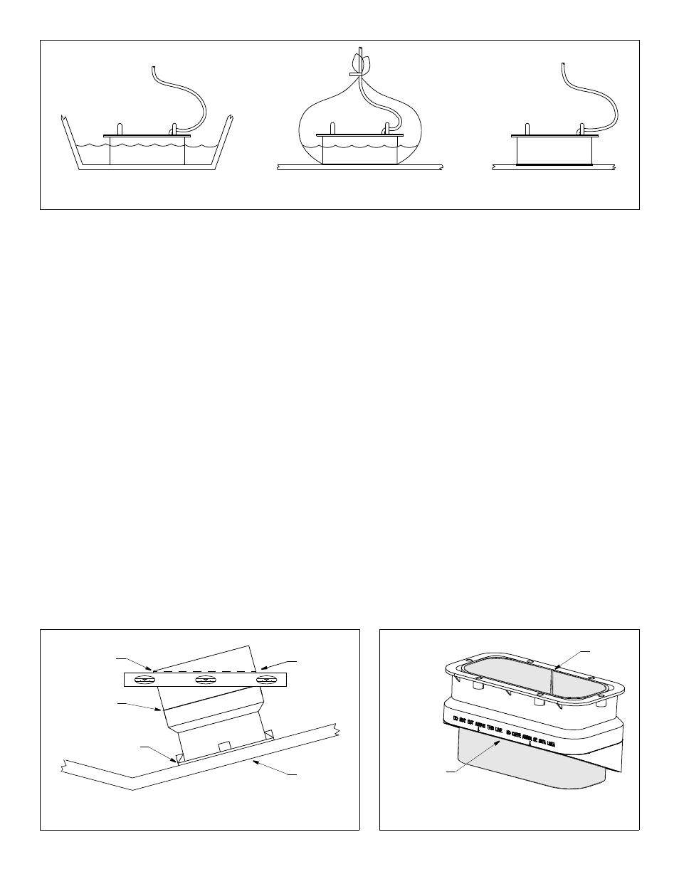
C.For any location—If the hull surface is not smooth, grind it with
a disc sander. Coat the active face of the transducer with a
water-based lubricant (such as K-Y
®
jelly). With a twisting
motion, press the face firmly against the hull (see Figure 5-C).
After testing, wipe away all traces of the lubricant from the
transducer’s face.
Observe the echosounder’s performance and compare it to the
baseline. Look for a stable depth reading that is similar to the
baseline. Compare the thickness and intensity of the bottom
trace.
If the performance is close to the baseline, this is a good mounting
location. Remember, some energy is lost transmitting through the
hull. If the test reading differs markedly from the baseline, you will
need to find another location to install the transducer.
NOTE: If there is no reading or it is erratic, the transducer may be
positioned over coring which is absorbing the acoustic energy.
Choose another location. If no other location is available, check
with the boat manufacturer to be certain coring is present.
Installation
Marking & Cutting
CAUTION: For optimal performance, the transducer must be
installed so the beam will be aimed straight down. This is
accomplished by cutting the tank to match the deadrise angle of
the hull.
CAUTION: Do not mark or cut the tank in the space labeled
“Do not cut above this line.”
1. When you are satisfied that the selected mounting location is
optimal, place the tank up-side-down on the hull (see Figure 6).
NOTE: The tank can be placed with either a short side or long
side parallel to the centerline of the boat.
2. Holding a carpenter’s level even with the lower corner of one of
the sides to be cut, draw a level line on the tank. Repeat this
process on the opposite side of the tank. Connect these two
lines to form the SHORTEST side of the tank. Be sure the lines
are level, as they will be the cutting guidelines.
3. Before cutting the tank, be sure the TALLEST side will be
closest to the centerline (keel) of the boat after the tank is
installed. And be sure to observe the “Do not cut above this
line” mark.
Using a saw, cut the three sides of the tank along the guidelines
drawn. It may be necessary to further shape the tank to the hull
to ensure a liquid-tight bond.
4. The tank is provided with a cork liner to reduce sound echoes.
After the tank has been cut, wrap the cork liner around the
inside of the tank (see Figure 7). Butt the sides of the liner along
the center of the tallest side. Trace the bottom edge of the tank
onto the liner.
NOTE: There may be a gap between the butted edges which
will not affect performance.
5. Remove the cork liner from the tank. Use scissors to cut the
liner along the line drawn.
Figure 5. Testing the transducer at the selected location
A
B
C
Figure 7. Fitting the cork liner
(22° angle shown)
Figure 6. Marking the cutting guidelines
starting at the
top
hull
of tank
carpenter’s
lower corner.
level
Draw a level line
3
Copyright © 2006 Airmar Technology Corp.
Copyright © 2006 Airmar Technology Corp.
Copyright © 2006 - 2011 Airmar Technology Corp.
Do not mark
below this line.
trace bottom
edge of tank
onto cork liner
possible
gap