Testing the selected mounting location, Selecting the adhesive – Airmar P72 User Manual
Page 2
Testing the Selected Mounting Location
Establishing a Performance Baseline
The results of this test are used as a basis of comparison to
determine the best in-hull location for the transducer.
1. Take the boat to the maximum depth in which you will be
operating the echosounder. If deep water is not available, find a
location with at least 15m (50').
2. Connect the transducer to the echosounder.
3. Tape the transducer to a pole, cable side up. Do not tape over
the active face. Hold the transducer over the side of the boat
with the active face fully submerged and parallel to the water
surface (see Figure 2).
4. Observe the echosounder’s performance and the gain setting
required to obtain a reading on the display. Record the depth
reading.
Testing the Location
While the boat is at the same site (depth of water), test the
transducer inside the hull at the mounting location. Use one of the
test methods below.
A.For a location near the stern and a minimal deadrise angle—
Clean away any build-up of grease and/or dirt with detergent or
alcohol. Place the transducer against the hull and allow bilge
water to cover the surface where they touch (see Figure 3A).
B.For a greater deadrise angle—If the hull surface is not smooth,
grind it with a disc sander. Place the transducer inside a thin
plastic bag. Partially fill the bag with water and close it tightly with
a cable tie. Wet the surface of the hull and press the active face
of the transducer against it through the bag (see Figure 3B).
C.For any location—If the hull surface is not smooth, grind it with
a disc sander. Coat the face of the transducer with a water-
based lubricant (such as K-Y® jelly). With a twisting motion,
press the face against the hull (see Figure 3C) After testing,
wipe all traces of the lubricant from the transducer’s face.
Observe the echosounder’s performance and compare it to the
baseline. Look for a stable depth reading that is similar to the
baseline. Compare the thickness and intensity of the bottom trace.
If the performance is close to the baseline, this is a good mounting
location. Remember, energy is lost transmitting through the hull. If
the test reading differs markedly from the baseline, you will need
to find another location to install the transducer.
NOTE: If there is no reading or it is erratic, the transducer may be
positioned over coring that is absorbing the acoustic energy.
Choose another location. If no other spot is available, check with
the boat manufacturer to be certain coring is present before
proceeding with the instructions for “Installation in a Cored
Fiberglass Hull” on page 4.
Selecting the Adhesive
CAUTION: Do not use:
• “5 minute” epoxies because they are too brittle.
• RTV (silicone) adhesives because they absorb most of the
sound energy.
A hard adhesive, like the epoxy supplied, transmits sound best.
However, winter temperature extremes and flexing on trailer
rollers can cause it to delaminate. Soft adhesives absorb sound
and will greatly reduce performance. To compromise, use a
viscous slow-cure epoxy or a fairly rigid one-part adhesive
sealant. In cold climates, a one-part polyurethane adhesive, such
as Boat-Life’s Life Seal
®
, may be best.
2
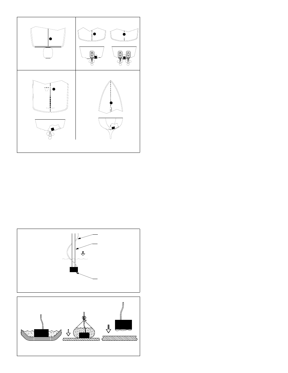
Figure 1. Selecting the mounting location
Outboard
Inboard/outboard
Inboard
Sailboat
Copyright © 2005 Airmar Technology Corp.
Boat Type
(see Figure 1)
Consult the boat manufacturer for the best transducer placement.
If this information is unavailable, follow the guidelines below.
When possible, mount on the side of the hull where the propeller
blades are moving downward.
• Outboard powerboats—Install as far aft as is practical.
• Inboard/outboard powerboats—Install close to the engine(s).
• Inboard powerboats—Install forward of the propeller(s) and
shaft(s).
• Sailboats—Install on or near the centerline and forward of any
fin keel 300 - 600mm (1 - 2').
Figure 2. Establishing a performance baseline
cable
pole
active face
Copyright © 2005 Airmar Technology Corp.
Figure 3. Testing at the selected location
A
B
C
Copyright © 2005 Airmar Technology Corp.