Installation, Cable routing & connecting, Installation in a cored fiberglass hull – Airmar P72 User Manual
Page 3: No yes, Yes no yes
Installation
Cored fiberglass hull—Follow separate instructions on page 4.
CAUTION: Do not proceed if the hull temperature is below 15
°
C
(60
°
F) because the cure time of the epoxy will be greatly extended.
CAUTION: Do not use adhesive to fill gaps between the
transducer and the hull since this will greatly reduce the
transducer’s performance (see Figure 4).
1. The hull surface to be bonded must be flat, smooth, and free of
paint or any other finish. If the surface is rough, use a disk
sander to smooth an area 10cm (4") in diameter.
2. To ensure a tight bond, remove any dust, grease, or oil from the
hull surface and the bottom of the transducer with detergent or
alcohol. Dry both the selected area and the transducer.
3. If the hull temperature is above 15
°
C (60
°
F), mix the epoxy
until the color is uniform.
4. Apply the epoxy to the center of the transducer’s active face—
the flat side opposite the cable.
5. Press the transducer face onto the hull with a twisting motion to
expel all air bubbles. Do not use adhesive to fill gaps (see
Figure 4, 5, or 6). (If the hull is slanted, temporarily secure the
transducer in place with duct tape.) The adhesive is cured in 24
hours at 21
°
C (70
°
F). The lower the temperature the longer the
cure time.
Cable Routing & Connecting
CAUTION: If the transducer came with a connector, do not
remove it to ease cable routing. If the cable must be cut and
spliced, use Airmar’s splash-proof Junction Box No. 33-035 and
follow the instructions supplied. Removing the water-proof
connector or cutting the cable, except when using a water-tight
junction box, will void the transducer warranty.
1. Route the cable to the echosounder being careful not to tear the
cable jacket when passing it through the bulkhead(s) and other
parts of the boat. Use grommet(s) to prevent chafing. To reduce
electrical interference, separate the transducer cable from other
electrical wiring and the engine(s). Coil any excess cable and
secure it in place with cable ties to prevent damage.
2. Refer to your echosounder owner’s manual to connect the
transducer to the instrument.
Installation in a Cored Fiberglass Hull
Installation in a cored hull is difficult. The objective is to bond the
transducer to the inside surface of the hull’s outer skin while
preventing any moisture from penetrating the core.
CAUTION: There is no way to determine if the outer skin is solid
(no trapped air bubbles in the fiberglass resin) at the selected
location before cutting the inner skin.
CAUTION: Do not proceed if the hull temperature is below 15
°
C
(60
°
F) because the cure time of the epoxy will be greatly extended.
CAUTION: Do not use adhesive to fill gaps between the
transducer and the hull since this will greatly reduce the
transducer’s performance.
1. Using a 78mm or 3" hole saw, cut through the inner skin and the
core at the selected location (see Figure 7). The core material
can be very soft. Apply only light pressure to the hole saw after
cutting through the inner skin to avoid accidentally cutting the
outer skin.
3
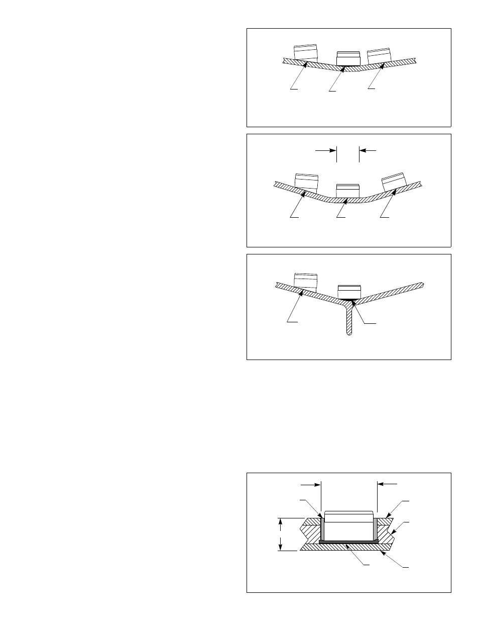
Figure 7. Installation in a cored fiberglass hull
(P76 shown
)
inner skin
core
outer skin
pour in
casting
epoxy
78mm (3")
epoxy
hull thickness
Copyright © 2005 Airmar Technology Corp.
2. Remove the plug of core material so the inner core of the hull is
fully exposed. Sand the inside surface of the outer skin using a
miniature disk sander (Dremel Moto-Tool). Slightly undercut the
surrounding coring if possible.
3. Clean and dry both the inside surface of the outer skin and the
face of the transducer with detergent or alcohol to remove any
dust, grease, or oil.
4. If the hull temperature is above 15
°
C (60
°
F), mix the epoxy
until the color is uniform.
Figure 4. Deadrise angle of 10
°
or less
P78
P76
NO
Do not use adhesive
to fill gaps.
NO
YES
Copyright © 2005 Airmar Technology Corp.
YES
NO
YES
76 mm (3")
flat area
P78
Figure 5. Deadrise angle from 10
°
–22
°
and flat centerline
P76
Copyright © 2005 Airmar Technology Corp.
angle too
steep
NO
YES
P76
P78
Do not use
Figure 6. Sailboat with fin keel & deadrise angle from 10
°
–22
°
adhesive to
fill gaps.
Copyright © 2005 Airmar Technology Corp.
(or P72)
(or P72)
(or P72)