Airmar, Trolling motor mount, Transducer replacement – Airmar P72 User Manual
Page 4
4
Copyright © 2004 - 2012 Airmar Technology Corp. All rights reserved.
5. Pour the epoxy into the cavity to a depth of 6mm (1/4") and
immediately set the transducer in place with a firm twisting
motion to expel all air bubbles. Do not use adhesive to fill
gaps.
6. Mix a half cup of casting epoxy following the manufacturer’s
directions. Stir carefully to avoid trapping air in the mixture.
Pour this around the transducer until the cavity is full. Permit the
casting epoxy to set for at least 1 hour. If the cavity is at an
angle, as is usual, tape over the lower portion of the cavity. Mix
more epoxy and pour until the cavity is filled flush with the top of
the inner skin. If the transducer is covered with casting epoxy,
be sure the cable is bonded tightly so that no water seeps into
the core.
7. You may grind the surface smooth, if necessary, but do not
damage the cable.
8. If there is doubt as to the strength of the area, apply layers of
fiberglass overall to a satisfactory thickness. Be sure bilge
water cannot enter the core at the cable.
Trolling Motor Mount
Applications
• Electric trolling motor with diameter from 77–95mm (3–3-3/4")
• Can be adapted for use with smaller or larger motor cases
Tools & Materials
Safety goggles
Band clamp (some installations)
Cable ties
Location
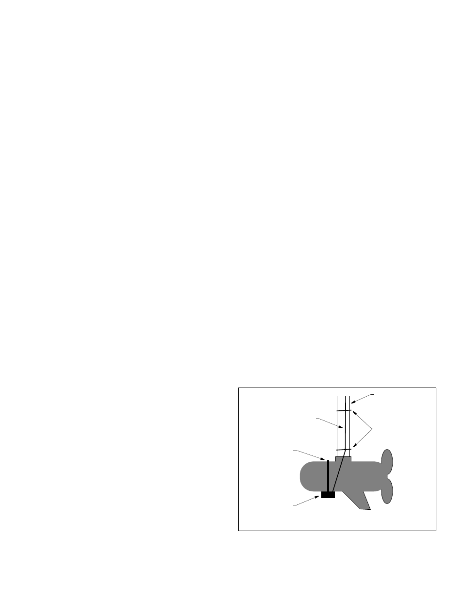
Locate the transducer under the motor case (see Figure 8).
NOTE: If the motor has a strut that shades the transducer, it will
not significantly reduce the transducer’s performance.
Installation
Small motor case [64mm (2-1/2")]: Do not to over tighten the
band clamp causing the tabs on the transducer housing to break.
Large motor case [102mm (4")]: Purchase a larger stainless steel
band clamp in the plumbing supply section of most hardware stores.
1. Loosen the screw in the band clamp so that one end of the band
is free.
2. Wrap the band clamp around the motor case. Tighten the screw.
Routing the Cable
CAUTION: Do not put tension to the cable as it exits the
transducer, as excessive force can break internal connections.
CAUTION: On bow mounted motors, be sure the cable route does
not result in pinching the cable when the motor is in the UP position.
1. Route the cable around the side of the motor case and along the
support tube (see Figure 8).
2. Secure the cable to the support tube with cable ties.
3. Route the cable to the echosounder being careful not to tear the
cable jacket. To reduce electrical interference, separate the
transducer cable from other electrical wiring.
AIRMAR
®
TECHNOLOGY CORPORATION
35 Meadowbrook Drive, Milford, New Hampshire 03055-4613, USA
www.airmar.com
support tube
band clamp
transducer
cable
cable ties
4. To prevent damage, coil any excess cable and secure it in
place with cable ties.
Maintenance & Repair
Keep the transducer free of marine growth and petroleum residue.
To clean use a soft cloth and mild household detergent.
Damaged Cable Jacket
1. Should the outer jacket of the cable be abraded or cut, check
that the internal conductors are not damaged.
2. If the conductors are damage free, allow the cable to dry and fill
the damaged area with sealant.
3. Cover the damaged area with electrical tape.
Severed Cable
1. Slide heat-shrink tubing onto the cable.
2. Splice each pair of matching colored conductors with rosin
core solder.
3. Wrap each conductor with insulating tape at the splice.
4. Splice the shield (braided) wire with solder.
5. Fill the spliced area in the cable with sealant.
6. Cover the damaged area with the heat-shrink tubing and follow
the manufacturer’s directions for its use.
NOTE: If the instrument fails to provide a reading, the problem
may not be the damaged cable; the transducer, connector or
instrument could be defective.
Transducer Replacement
The information needed to order a replacement Airmar transducer
is printed on the cable tag. Do not remove this tag. When ordering,
specify the part number, date, and frequency in kHz. For con-
venient reference, record this information at the top of page one.
Obtain parts from your instrument manufacturer or marine dealer.
Gemeco
Tel: 803-693-0777
(USA)
Fax: 803-693-0477
email: [email protected]
Airmar EMEA
Tel: +33.(0)2.23.52.06.48
(Europe, Middle East, Africa) Fax: +33.(0)2.23.52.06.49
email: [email protected]
Figure 8. Location and installation
Copyright © 1998 Airmar Technology Corp.