Installation, Preparation, Mounting – Airmar S69—Transom Mount User Manual
Page 2
Installation
CAUTION: Measure and drill carefully, since the bracket is only
slightly adjustable.
CAUTION: To prevent drilling too deeply, wrap masking tape
around the bit 22mm (7/8") from the point.
CAUTION: Fiberglass hull—Minimize surface cracking by
running the drill in reverse until the gelcoat is penetrated.
NOTE: If the adjustable paddlewheel assembly separates from
the bracket, refer to Figure 10 on page 4 to reassemble.
Preparation
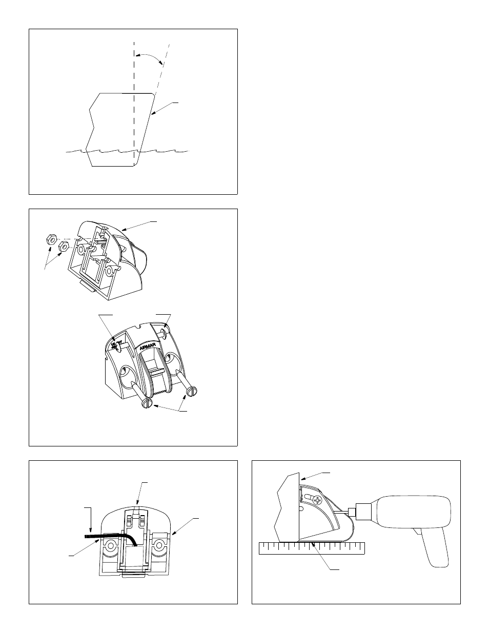
1. Measure the transom angle of the hull at the selected location
using a digital level (see Figure 2).
2. Insert the two nuts into the slots in the back of the bracket.
Install the #8 adjustment screws (see Figure 3).
Do not tighten the screws at this time.
3. There are three possible cable exits in the back of the bracket:
left, center, and right (see Figure 4). Choose the best cable exit
for your installation and route the cable through the notches in
the back of the bracket.
Mounting
CAUTION: The bottom edge of the adjustable paddlewheel assem-
bly (not the bracket) must be flush with the bottom of the hull.
1. The hull surface must be free of any dust, oil, grease, or loose
paint. Clean the selected location with a weak solvent (alcohol).
2. At the selected location and FLUSH with the bottom of the hull,
stick the double-sided tape to the transom (see Figure 1). Peel
off the remaining non-stick layer.
3. Holding a straight edge against the bottom of the hull, position
the sensor at the selected location (see Figure 5). The bottom
edge of the paddlewheel assembly (not the bracket) must
be flush with the bottom of the hull. Press the bracket firmly
in place. Use additional double-sided tape if necessary.
4. Using a 5.4mm, #3, or 13/64" drill bit, drill the two mounting holes
perpendicular to the transom. To prevent drilling too deeply, wrap
masking tape around the bit 13mm (1/2") from the point.
5. Apply marine sealant to the two, #10 x 1-1/4", mounting screws
to prevent water seeping into the transom. Screw the sensor to
the hull (see Figure 3). Check again that the bottom edge of the
paddlewheel assembly (not the bracket) is flush with the bottom
of the hull. If necessary, slide the bracket up or down. Tighten
the screws. Do not over tighten.
2
Figure 2. Measuring the transom angle
Figure 4. Routing the cable in the bracket
Figure 3. Installing the adjustment and the mounting screws
#8 adjustment
transom
angle
perp
endicul
ar
to
the
waterlin
e
transom
screws
nuts
bracket
#10 mounting
screws
Figure 5. Positioning the sensor
adjustable paddlewheel
assembly (not the bracket)
is flush with the hull bottom
transom
hold drill
perpendicular
to transom
cable exit
cable exit
cable routed
through a side
cable exit
cable exit
back view