Testing on the water, Cable routing, Adjusting – Airmar S69—Transom Mount User Manual
Page 3
Adjusting
CAUTION: Filling the gap between the sensor and the hull is
critical to the proper operation of the sensor.
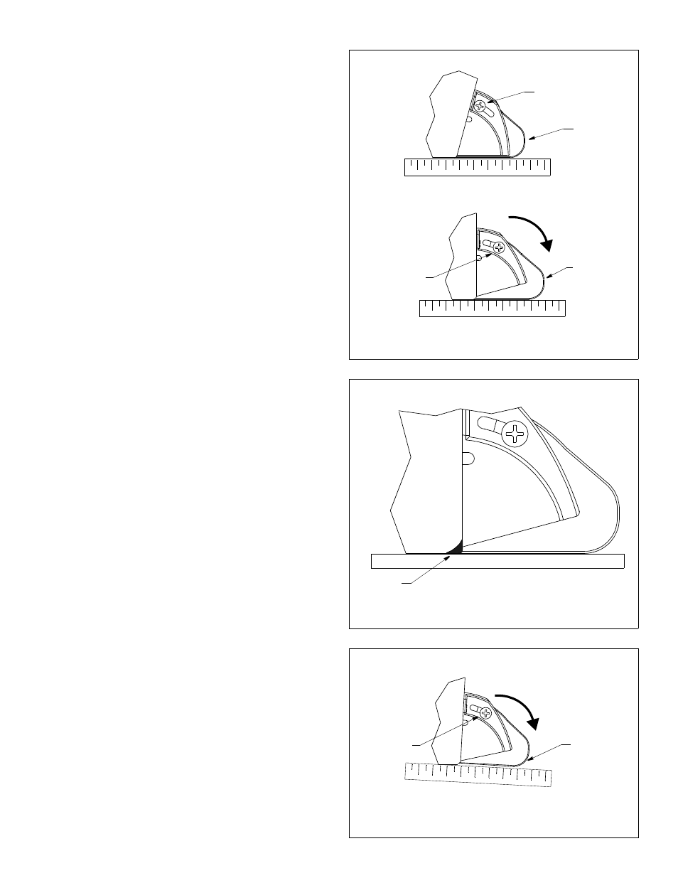
1. Holding a straight edge against the bottom of the hull, push the
adjustable paddlewheel assembly down until it touches the
straight edge and is flush with the bottom of the hull (see Figure
6). Tighten the adjustment screws to 1/4 turn past snug. Do not
over tighten.
2. Fill the gap between the sensor and the hull with marine sealant
using a putty knife for smoothing (see Figure 7). Pay particular
attention to the transition from the hull to the adjustable
paddlewheel assembly. This will ensure smooth water flow over
the paddlewheel.
Testing on the Water
1. Become familiar with your echosounder’s performance at a
speed of 4kn (5MPH).
2. Gradually increase the boat speed and observe the gradual
decline in performance due to turbulent water flowing over the
transducer’s active surface.
3. If the decline in performance is sudden (not gradual), identify
the boat speed at which the onset occurred. Return the boat to
this speed, then gradually increase speed while making
moderate turns in both directions.
4. If the performance improves while turning to the side on which
the sensor is installed, the transducer’s position probably needs
adjustment. It is probably in aerated water.
To improve performance, try the following one at a time in the
order given.
a. Increase the sensor’s angle in the water. Tilt the adjustable
paddlewheel assembly down 2° - 3° or until it is 3mm (/8”)
lower than the bottom of the hull (see Figure 8).
b. Move the sensor deeper into the water if possible.
c. Move the sensor closer to the centerline of the boat.
Fill unused screw holes with marine sealant.
NOTE: High-speed operation [above 35kn (40MPH)] may
require less projection in the water to improve performance and
reduce the chance that water pressure will cause the bracket to
release.
5. Calibration—To match the speed shown on the display to the
actual speed of the boat, you may need to calibrate the
instrument. Refer to your instrument owner’s manual.
Cable Routing
CAUTION: Do not remove the connector to ease cable routing. If
the cable must be cut and spliced, use Airmar’s splash-proof
Junction Box No. 33-035 and follow the instructions provided.
Removing the waterproof connector or cutting the cable, except
when using a water-tight junction box, will void the sensor
warranty.
Route the sensor cable over the transom, through a drain hole, or
through a new hole drilled in the transom above the waterline.
1. If a hole must be drilled, choose a location well above the
waterline (see Figure 1). Check for obstructions such as trim
tabs, pumps, or wiring inside the hull. Mark the location with a
pencil. Drill a hole through the transom using the appropriate
size bit to accommodate the connector.
2. Route the cable over or through the transom.
3
Figure 7. Filling the gap
Figure 6. Angle adjustment
16° transom
3° transom
push
marine
sealant
adjustment
screw (2)
adjustment
screw (2)
adjustable
paddlewheel
assembly
adjustable
paddlewheel
assembly
push
adjustment
screw (2)
adjust
paddlewheel
assembly
Figure 8. Tilting the adjustable paddlewheel assembly
33mm (1/8")
lower than
bottom of hull