A. one-cable triducer, Multisensor, B. all splices – Airmar Splash-proof Junction Box User Manual
Page 2: Preparing
2
A. One-cable TRIDUCER
®
Multisensor
NOTE: These instructions are not for use for with zip-cable (follow
instruction B).
Preparing
CAUTION: Take care not to damage the inner wires. when slitting
the jacket.
1. Disconnect the multisensor from the instrument.
2. Select the point where the cable will be spliced and mark the
jacket.
3. Place the cable on a hard, flat surface. At the marked location,
cut a 127mm (5") long slit in the cable JACKET only.
DO NOT CUT ANY WIRES AT THIS TIME.
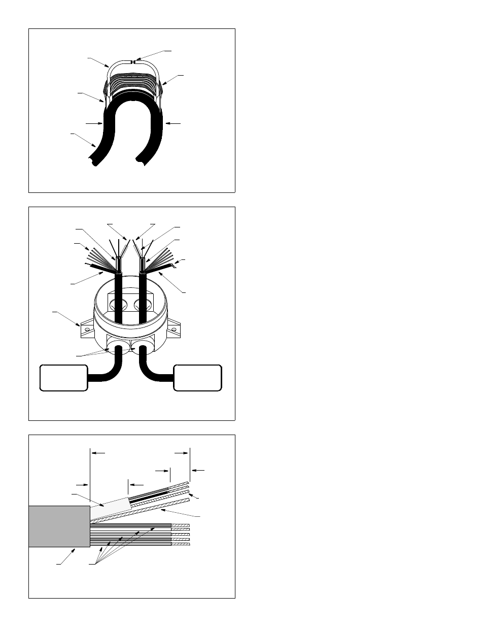
4. At the slit, bend the cable in half and remove the outer foil shielding
to expose the shielded pair(s) inside (see Figure 2). Lift one
shielded pair away from the other wires. Being careful not to allow
the shielded pair or the cutting pliers to touch the outer bare wire,
CUT ONLY THE SHIELDED PAIR. Repeat this process until all
the shielded pairs are cut. (This will allow any built-up electrical
charge stored in the transducer to be discharged.)
5. Cut the remaining single wires and the outer bare wire.
6. Cut away the slit segment of the cable jacket and the outer foil
shielding between the points marked “X”.
NOTE: If the multisensor has not been installed, do so at this
time following the instructions provided with it.
7. Apply alcohol to each cable jacket to ease sliding. Carefully
push approximately 203mm (8") of each cable end through a
large grommet (marked 5-7) (see Figure 3).
8. Separate the shielded pair(s) from other wires and remove
38mm (1-1/2") of the inner foil shielding (see Figure 4).
9. Strip 13mm (1/2") of insulation from the end of each insulated
wire to make a stripped end.
10.Slide a large diameter clear sleeve over the foil shielding of the
shielded pair(s) until it touches the cable jacket. If there is a
bare wire in the shielded pair, slide-on a small diameter clear
sleeve until it touches the large diameter sleeve. Slide a black
sleeve over the outer bare wire of each cable and position it
against the cable jacket (see Figure 3).
NOTE: For ease in holding the sleeves in place and connecting
to the terminals, fold the stripped ends to about half their
original length, twist the ends, and bend them 90
°
.
11.Go to “Connecting” on page 3 and follow the instructions.
B. All Splices
—
Except One-cable TRIDUCER
®
Multi-
sensor (follow instruction A)
Preparing
1. Disconnect the sensor(s) from the instrument.
2. Select the point(s) where the cable(s) will be spliced and mark
the jacket(s) with a pencil.
NOTE: With zip-cable, split the cable into two separate cables
for a distance of 0.5m (18") at the selected junction-box location
(see Figure 5).
3. At the marked location(s), cut each cable ONE AT A TIME.
(When the depth cable is cut, any built-up electrical charge
stored in the transducer will be discharged.)
NOTE: If the sensor(s) has not been installed, do so at this time
following the instructions provided with the product(s).
X
X
Figure 2. Cutting the TRIDUCER
®
multisensor cable
shielded pair
cut
outer bare
cable
foil
wire
CAUTION: Proceed with care!
jacket
shielding
Copyright © 2009 Airmar Technology Corp.
sensor
large diameter
Figure 3. Applying the sleeving (C332 cable shown)
small diameter
clear sleeve
clear sleeve
single wires
shielded pair
instrument
bare wire
tab
(marked 5-7)
large grommets
black sleeve
outer bare
wire
folded
stripped end
Copyright © 2009 Airmar Technology Corp.
Figure 4. Preparing the cut ends of the cable
Copyright © 2009 Airmar Technology Corp.
64mm (2 1/2")
remove cable jacket and
inner foil
13mm
(1/2")
25mm (1")
cable
jacket
C332
single
wires
shielded pair
bare
wire
outer
bare wire
or braid
remove
insulation
outer foil shielding