Connecting, Closing & mounting – Airmar Splash-proof Junction Box User Manual
Page 3
3
4. Apply alcohol to each cable jacket to ease sliding. Carefully
push approximately 203mm (8") of each cable segment through
the appropriate grommet (see Table 1 on page 4).
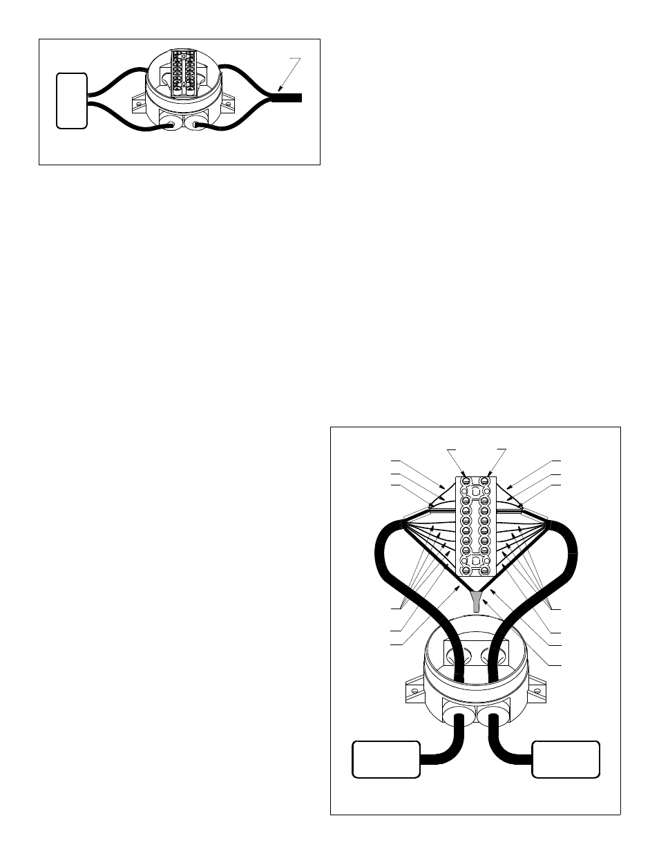
NOTE: Zip-cable uses one small grommet (marked 3-5) and one
large grommet (marked 5-7) (see Figure 5).
5. Strip 64mm (2-1/2") of the cable jacket and foil shield from each
cable end (see Figure 4).
NOTE: If the shielding is made of wire braid, make a hole in the
braid near the jacket and pull the inner wires out through the
hole. Twist the hollow braid to form an outer bare wire.
6. If there is a shielded pair(s), separate the shielded pair(s) from
other wires and remove 38mm (1-1/2") of the inner foil
shielding.
7. Strip 13mm (1/2") of insulation from the end of each insulated
wire to make a stripped end.
8. If there is a shielded pair(s), slide one large diameter clear
sleeve over the foil shielding of each shielded pair until it
touches the cable jacket (see Figure 3). If there is a bare wire in
the shielded pair, slide-on a small diameter clear sleeve until it
touches the large diameter sleeve. Slide a black sleeve over the
outer bare wire of each cable and position it against the cable
jacket.
NOTE: For ease in holding the sleeves in place and connecting
to the terminals, fold the stripped ends to about half their
original length, twist the ends, and bend them 90
°
.
Connecting
CAUTION: If there is a depth transducer, always connect it first
(the blue, black, or purple wires that are sometimes grouped in
shielded pairs)
CAUTION: Take care when matching like colored wires; there
may be wires with stripped insulation. Be sure to connect blue
stripe to blue stripe, solid blue to solid blue, black stripe to black
stripe, and solid black to solid black.
CAUTION: Make certain the sleeving completely covers any bare
wire so there are no frayed strands or loose ends to cause
shorting. If any bare wire is visible, shorten the stripped end and
reconnect it to the terminal.
1. Connect the depth function/sensor, if any, before the speed/
temperature function/sensor. Starting with terminal one, connect
each colored wire and bare wire in turn to the terminal block (see
Figure 6). Insert each wire through a separate square opening in
the side. Tighten the terminal screw until the wire is held firmly in
place.
2. Connect the matching colored wires and bare wire(s) from the
instrument cable to the correspondingly numbered terminals on
the opposite side of the terminal block. (Example: blue at
terminal 1 to blue at terminal 1 on the opposite side of the
terminal block)
NOTE: If there are nine wires in the cables, twist the outer bare
wires together, dip the ends in petroleum jelly, cover them with a
crimp connector, and crimp the connector in place with crimping
pliers.
With ten wires, twist the two brown wires together, twist the two
white wires together, then crimp each pair as described above.
Closing & Mounting
1. From outside the junction box, carefully pull each cable until only
25mm (1") of the cable jacket remains inside the box. This will
invert the nipples to seal the grommets.
2. Place the terminal block in the box and secure the ends with the
terminal block screws provided (see Figure 1).
NOTE: If there is a crimp connection(s), push it into the junction
box first, under the terminal block.
3. Arrange the wires neatly in the junction box.
4. Close the box with the red cap. Expel the excess air inside the
box by placing a thumb on the center of the red cap and
applying pressure for 3 seconds.
5. Screw the junction box to the selected mounting surface at the
holes previously drilled. Use the two mounting screws provided.
6. Coil any excess cable and secure it in place using cable ties to
prevent damage.
7. Connect the cable to the instrument.
Figure 5. Zip-cable splice
instrument
zip-cable
Copyright © 2009 Airmar Technology Corp.
Figure 6. One-cable multisensor splice (C332 shown)
multisensor
instrument
outer bare
speed/temp
(red, green,
white, brown)
(with sleeve)
depth:
blue or purple
black
outer bare
speed/temp
(red, green,
white, brown)
(with sleeve)
1
1
2
2
3
3
4
4
5
5
6
6
7
7
8
8
terminal 1
Copyright © 2009 Airmar Technology Corp.
smart (orange)
smart (orange)
crimp connector
bare with sleeve
depth:
blue or purple
black
bare with sleeve
on terminal
block