Installation ls timing cover conversion kit – Allstar Performance ALL90090 User Manual
Page 2
Allstar Performance 8300 Lane Dr., Watervliet, MI 49098
Phone: (269) 463-8000 Fax: (800) 772-2618 www.allstarperformance.com
Form 1122
Page of 5
Rev. 120412
other Considerations:
Most LS engines have interference fit dampeners and do not have a keyway retainer. Therefore, an aftermar-
ket dampener must be purchased (except CT525 crate engines). It is also recommended to have crankshaft
pinned for circle track applications and other applications with high inertia loads. ATI offers a drill fixture kit
(part no. 918993) for drilling the crankshaft to accept a pin to work with ATI and other keyed dampeners.
OE style accessories and pulley systems will not work in conjunction with this timing cover conversion kit
due to the requirement of an aftermarket dampener with degree marks for timing purpose and additional
length of the timing cover and water pump. Water pump spacers and a standard rotation water pump will
be required as the timing cover protrudes out further than stock OE cover.
Instructions for conversion kit begin at the timing cover removal
assuming water pump, accessories and fluids are already removed from engine.
1.
Remove retaining bolt holding dampener in place then remove dampener using appropriate puller.
2.
Remove eight timing cover fasteners holding cover to block and two fasteners attaching oil pan to
cover (retain fasteners for installation of new cover.) Use caution removing cover not to damage the
gasket as it will be re-used.
3.
With the timing chain and gears now visible, rotate crankshaft until dot or timing mark on cam gear
is at the 6 o'clock position. Timing marks on cam gear and crankshaft gear should be aligned. If no
marks are visible on crank gear, place alignment mark on crank gear for reinstallation using a
permanent marker. This should place alignment pin on camshaft at approximately the three o'clock
position.
4.
Remove cam gear retaining bolts and remove cam gear, exposing
the cam retaining plate, be cautious of the thrust bearing behind
the cam gear (if applicable) and the direction of installation.
5.
The retaining plate needs to be removed and drilled to provide an
oil supply to keep the distributor gear well lubricated. Use the
template included on page 5 of these instructions. Center punch
on the two marks indicated and drill plate using a #72 or .025"
drill bit. Debur or chamfer holes to remove any loose material.
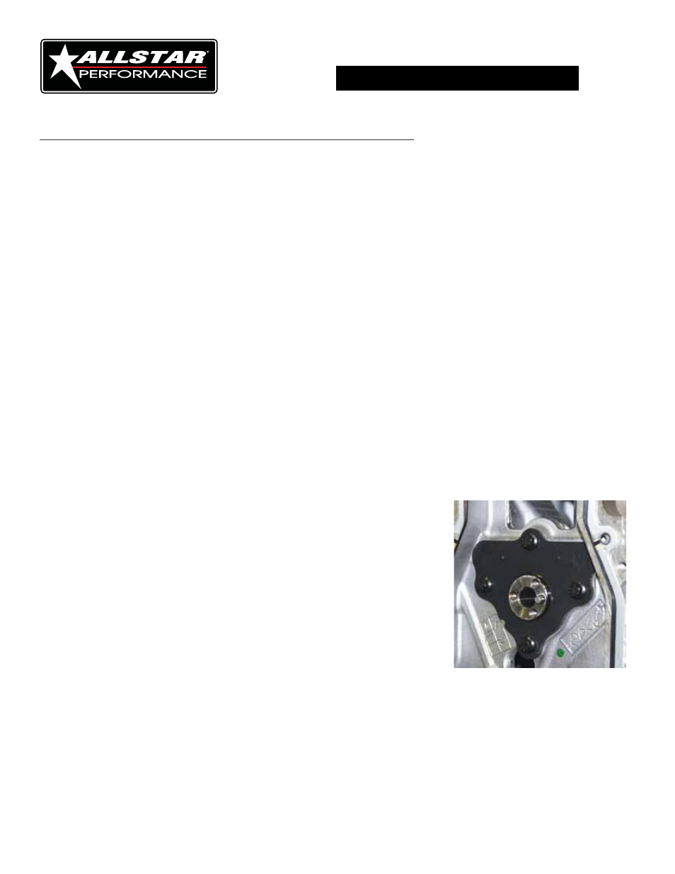
6.
Reinstall the cam retaining plate and torque fasteners to 18ft lbs.
(Figure #1).
STEPS 7-16 ARE PROVIDED WHEN DRILLING AND PINNING THE CRANKSHAFT.
PROCEED TO STEP 17 TO CONTINUE INSTALLATION WITHOUT MODIFING CRANKSHAFT.
Figure #1
installation
ls timing Cover Conversion Kit
2