Installation ls timing cover conversion kit – Allstar Performance ALL90090 User Manual
Page 3
Allstar Performance 8300 Lane Dr., Watervliet, MI 49098
Phone: (269) 463-8000 Fax: (800) 772-2618 www.allstarperformance.com
Form 1122
Page of 5
Rev. 120412
7.
Remove oil pan and oil pump pick-up.
8.
Remove oil pump, timing chain (noting direction of chain
for re-installation) and oil pump drive cam from crankshaft
snout to install ATI #918993 fixture (Figure #2).
9.
When drilling crankshaft it is important to drill and install
the pin in-line with crank timing gear and oil pump drive
cam keyway to ease installation/removal of gear and cam.
Installing the pin in-line with keyway also provides proper installation of an aftermarket keyed dampener.
10.
Using a marker or an awl and a straight edge extend the lines of the keyway to use as a reference to
install drill fixture (Figure #3). Center fixture hole over extended keyway marks using a flashlight to
view through fixture holes.
11.
Follow ATI instructions for drilling and pinning crankshaft. Use caution to prevent shavings and
debris from entering engine.
12.
Once crankshaft drilling and pinning is complete, reassemble.
13.
Install timing chain, oil pump cam onto crankshaft snout and install oil pump. Torque pump
mounting fasteners to 18 ft. lbs.
14.
Remove oil residue from mounting bolt threads and oil pump pickup mounting hole, apply a small
amount of blue thread locker to pick-up fastener and install oil pump pick-up to oil pump. Pickup
tube has a neoprene o-ring seal so use caution when installing. Torque fastener to 106 in. lbs.
15.
Clean oil pan surface and surface of engine block. Apply a small dab of silicone sealant to the two
areas where the rear cover meets the block to fill any voids.
16.
Install oil pan gasket and oil pan. Tighten fasteners to 18 ft. lbs.
17.
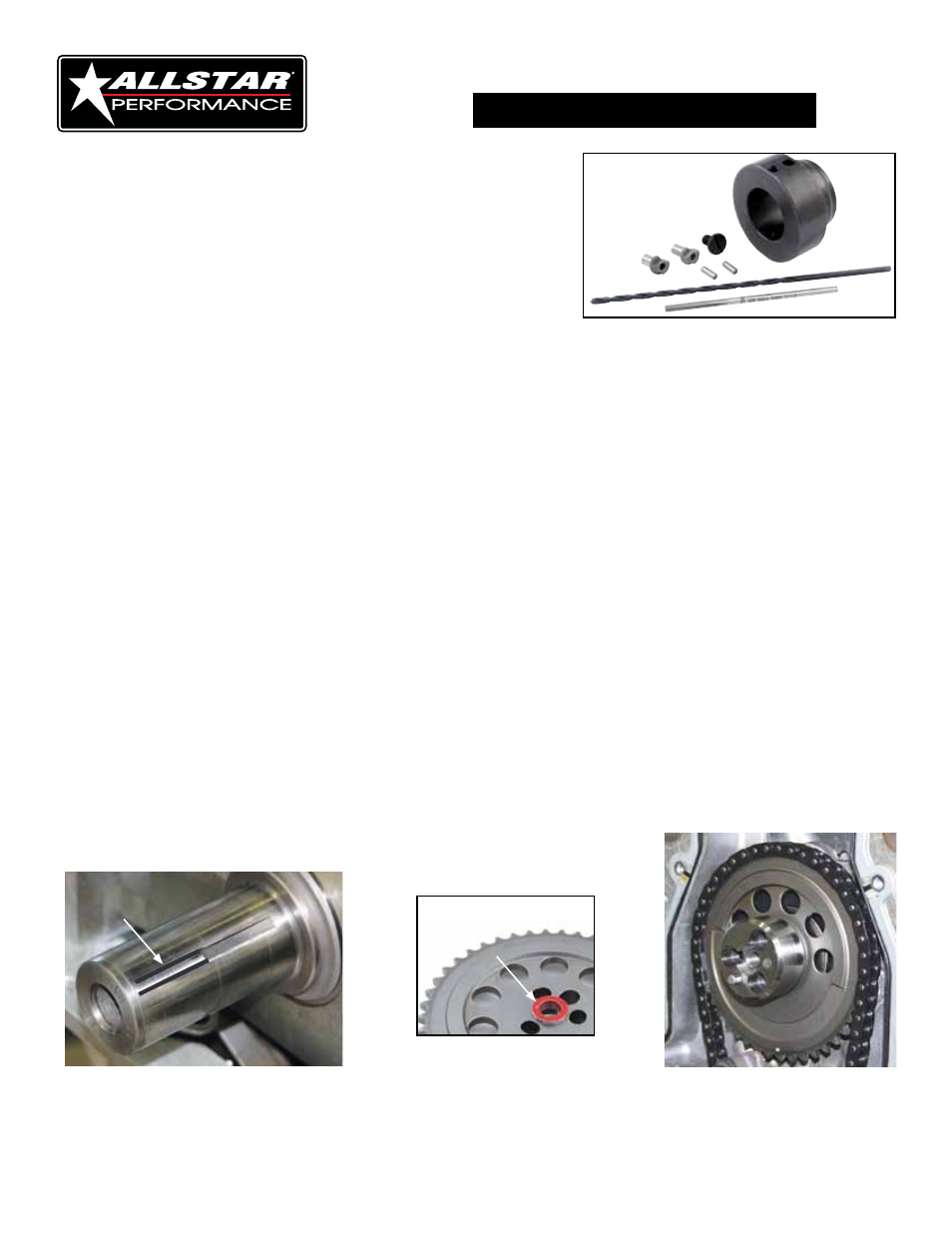
Select proper colored drive adapter bushing and insert stepped end into cam gear (Figure #4). Black
(.550" for LS2 cam gear), Green (.554" for LS1 and LS6 cam gear) and Red (.685" for most aftermarket
cam gears including Cloyes #9-3158A Hex-A-Just). Bushing should be tight in cam gear.
18.
Verify thrust bearing is positioned behind cam gear (if applicable) and install cam timing gear and
adapter with supplied 8mm-1.25 x 35mm socket head fasteners making sure to align timing marks.
Crank should be at 12 o'clock position and cam should be at 6 o'clock position (Figure #5). Remove
bolts one at a time and apply blue thread locker to each and torque to 26 ft. lbs.
Figure #2
ATI 918993
installation
ls timing Cover Conversion Kit
3
Figure #4
Figure #3
Figure #5