Servicing, Continued, Replacement of fan – Archgard 25-BVI20N-2 User Manual
Page 26: Disconnect the power to the appliance, Valve connections
25-BVI20N –2 26
REPLACEMENT OF FAN
Disconnect the power to the appliance.
Remove the louvers, control cover door, brick panels, logs and burner.
Remove the firebox lower back. Remove the screws located at the back of the firebox. Take the
lower firebox back out. Be careful not to damage the gasket. The fan is now visible.
Use a 11/32” hex socket and remove the three nuts holding the fan to the back of the firebox.
Disconnect the spade connectors to the fan. Carefully remove the fan.
Reverse the above instructions to install the new fan
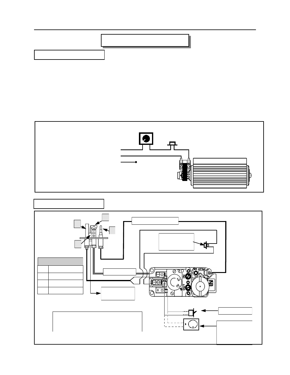
SPEED CONTROL
LINE
CONVECTION FAN
GROUND
110°F (43ºC) N.O.
THERMAL SNAP SWITCH
NEUTRAL
TO
APPLIANCE
120 VAC
WIRING DIAGRAM
SERVICING -
Continued
OPTIONAL
REMOTE SWITCH
OR
THERMOSTAT
ON/OFF SWITCH
WIRE TO PIEZO
(SPARKER)
B
A
C
D
212
0
F (100
0
C)
SPILL SWITCH
(MANUAL RESET)
SUPPLY TUBE
THERMOCOUPLE LEAD
A
ELECTRODE
B
THERMOPILE
C
PILOT CAP
D
THERMOCOUPLE
PILOT ASSEMBLY
ROBERTSHAW GAS CONTROL VALVE
WIRING DIAGRAM. USED FOR
EURO 25 INSERT.
VALVE CONNECTIONS