Rear panel – ARM Electronics ARM HR Series User Manual
Page 2
2
15 PLAY/STOP
Press once to start the playback of recorded video. Press again to exit.
16 MODE
Press this key to view in full-screen or multiple window modes.
17 SEARCH
Press this key to search recorded video by date/time or event.
18 MENU
Press this key to enter the OSD setup menu.
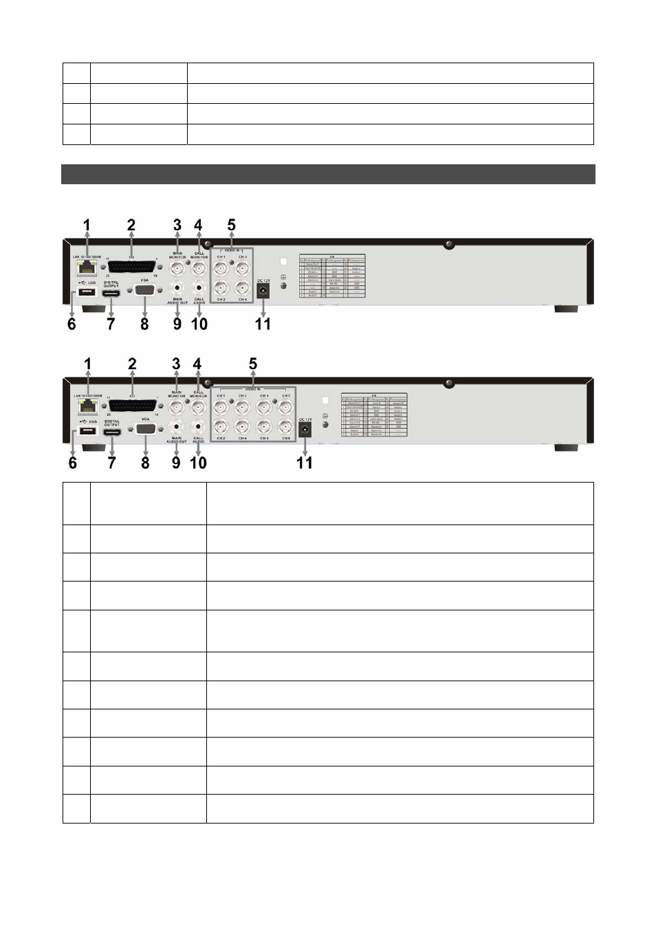
Rear Panel
4CH/8CH models:
1
LAN 10/100/1000M
(RJ-45)
The DVR is capable of networking. Once the unit is connected to the
LAN network, users can remotely access the DVR through the remote
software on a PC.
2
Alarm I/O, RS-485
& Audio In
The D-Sub connector provides alarm I/O, RS-485 & Audio In ports that
offer users the flexibility to connect required devices to the DVR.
3
Main Monitor –
BNC
The DVR can connect to a BNC monitor via the BNC connector.
4
Call Monitor
(BNC)
The BNC Call Monitor connector allows users to connect the DVR with
a call monitor.
5
Video In
(BNC)
A group of BNC connectors is provided for video input streams from
installed cameras. The DVR will detect video source of CH1 and
automatically adjust the system to NTSC or PAL video system.
6
USB Port
This USB port allows users to connect a USB mouse with PS/2
protocol.
7
Main Monitor –
Digital Output
The DVR can connect to a Digital Output monitor via an optional
Digital Output connector.
8
Main Monitor –
VGA
The DVR can connect a VGA monitor via the VGA connector.
9
Main Monitor
Audio Out
Main Monitor Audio Out RCA connectors are provided for the DVR to
connect audio output devices (e.g. amplified speakers).
10
Call Monitor
Audio Out
Call Monitor Audio Out RCA connectors are provided for the DVR to
connect audio output devices (e.g. amplified speakers).
11 Power Jack
The DVR has a free voltage DC power connection jack. Please
connect the power supply adapter shipped with the unit.