Pin definition of alarm i/o & rs-485 – ARM Electronics XR&HD480 Series User Manual
Page 3
3
13
LAN
10/100/1000M
(RJ-45)
The DVR is capable of networking and it allows the videos to be viewed
over the LAN network or the Internet by using the Internet Explorer.
14 RS232
The DVR provides a RS232 communication port for sending and
receiving signals.
15
Audio Out
(Optional)
Optional Audio Out connectors can be installed for each channel to
connect its individual audio output device.
16 Power
Switch Use this switch to power on / off the DVR.
17 Power
Jack
Connect the power supply cord shipped with the DVR. Use of other
power supply cords may cause overloading.
NOTE:
Refer to User’s Manual Appendix E: Simultaneous Output Options for detailed
information about monitor functionality.
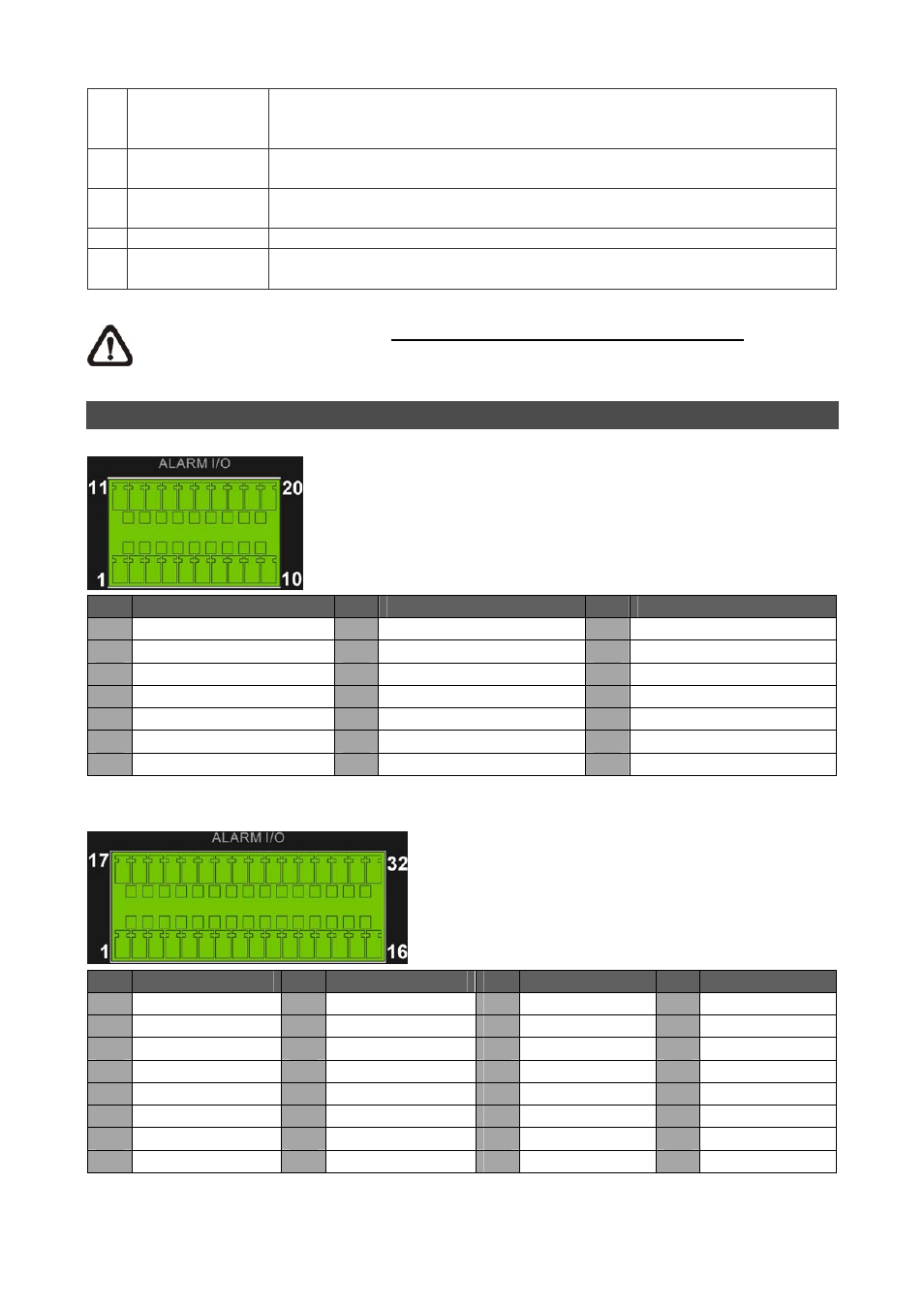
Pin Definition of Alarm I/O & RS-485
4ch-Model / 8ch-Model:
Pin Definition
Pin Definition
Pin
Definition
1
RS485 D+
8
Normal Close B
15
Alarm In 5 (8ch model)
2
RS485 D−
9
Common Node B
16
Alarm In 6 (8ch model)
3
Ground
10
Normal Open B
17
Alarm In 7 (8ch model)
4
Normal Close A
11
Alarm In 1
18
Alarm In 8 (8ch model)
5
Common Node A
12
Alarm In 2
19
N/A
6
Normal Open A
13
Alarm In 3
20
N/A
7
Ground
14
Alarm In 4
16ch-Model:
Pin Definition
Pin Definition
Pin
Definition
Pin Definition
1
RS485 D+
9
Common Node B
17
Alarm In 1
25
Alarm In 9
2
RS485 D−
10
Normal Open B
18
Alarm In 2
26
Alarm In 10
3
Ground
11
Ground
19
Alarm In 3
27
Alarm In 11
4
Normal Close A
12
Normal Close C
20
Alarm In 4
28
Alarm In 12
5
Common Node A 13 Common Node C
21
Alarm In 5
29
Alarm In 13
6
Normal Open A
14
Normal Open C
22
Alarm In 6
30
Alarm In 14
7
Ground
15
Ground
23
Alarm In 7
31
Alarm In 15
8
Normal Close B
16
Ground
24
Alarm In 8
32
Alarm In 16