Eneo PXD-5362F01IR User Manual
Page 14
Advertising
14
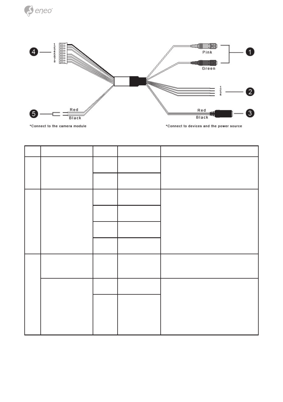
No. Connector
Pin
Definition
Remarks
1
Audio I/O
Pink
Line In
Two-way audio transmission
Green
Line Out
2
Alarm (4-Pin
Terminal Block)
1
ALM_IN –
Alarm connection
2
ALM_IN +
3
ALM_OUT –
4
ALM_OUT +
3
Power DC Jack
-
DC 12V
Power connection (Tip: +, sleeve:
-)
Power Wires
Red
AC 24V (+)
Remove DC Jack connector
head, and apply AC 24V with
Red and Black wires.
Please refer to the section of
Cable Definition in User’s Ma-
nual.
Black
AC 24V (–)
Advertising
This manual is related to the following products: