Connecting the monitoring cable – H3C Technologies H3C S10500 Series Switches User Manual
Page 41
31
7.
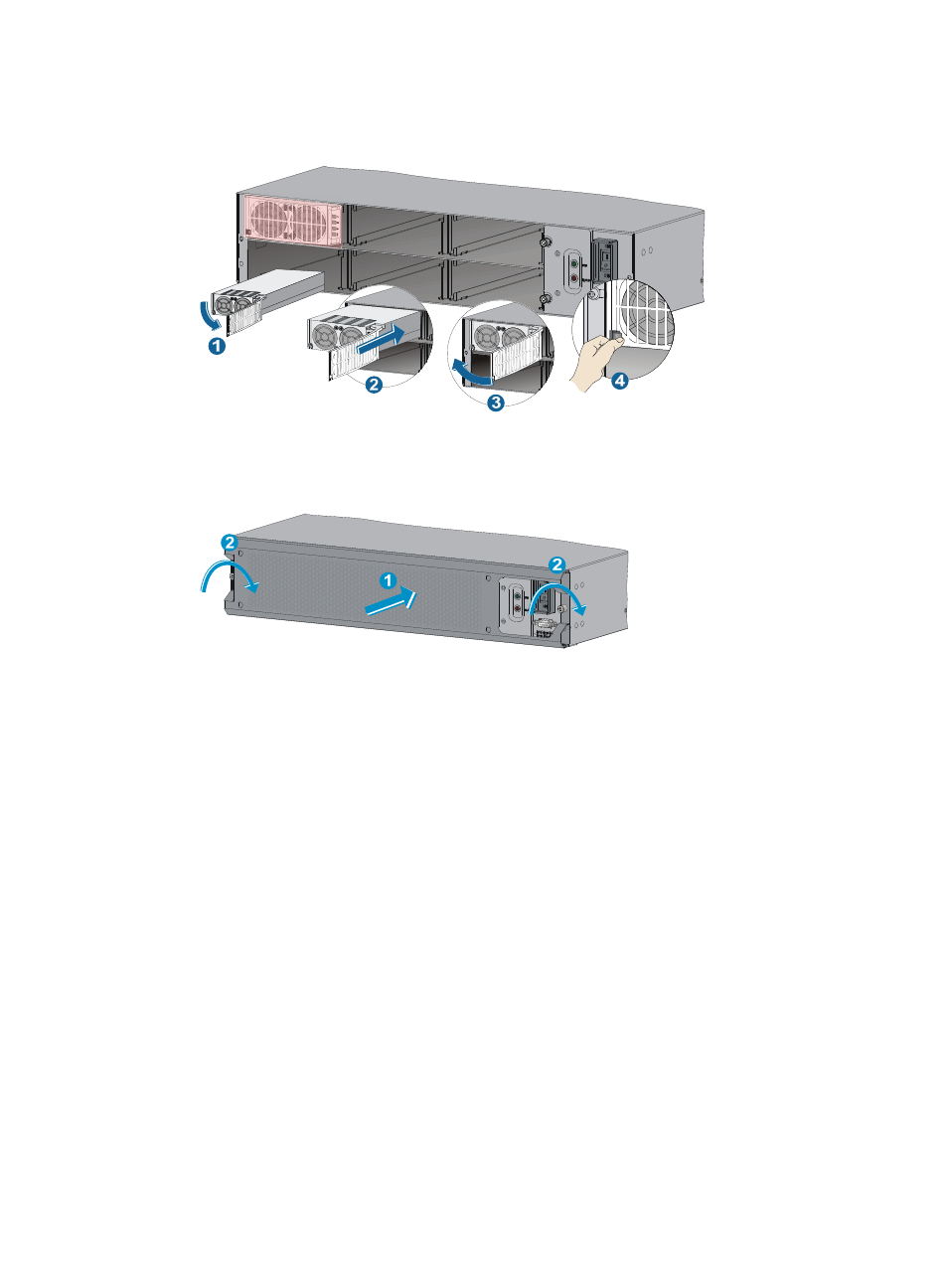
Repeat steps 3 to 5 to install other power modules.
Figure 30 Installing power modules
8.
Reinstall the front cover of the external PoE power frame and fasten the screws.
Figure 31 Installing the front cover
Connecting the monitoring cable
An external PoE power frame monitoring cable has two RJ-45 connectors. You can connect either of the
RJ-45 connectors to the RS485 port on the MPU if the switch has only one MPU. H3C recommends that
you use both RJ-45 connectors of the monitoring cable if the switch has two MPUs.
To connect the monitoring cable:
1.
Connect the DB-9 connector of the monitoring cable to the 9-core serial port on the external PoE
power frame, and fasten the screws.
2.
Connect an RJ-45 connector of the monitoring cable to the RS485 port on the MPU of the switch.