Basic concepts, Evb working mechanism – H3C Technologies H3C S6800 Series Switches User Manual
Page 9
2
EVB solves these limitations. It uses a physical switch (called EVB bridge) to switch traffic for VMs on a
directly connected physical server (called EVB station). EVB implements traffic monitoring, network
policy enforcement, and unified network deployment and management for VMs.
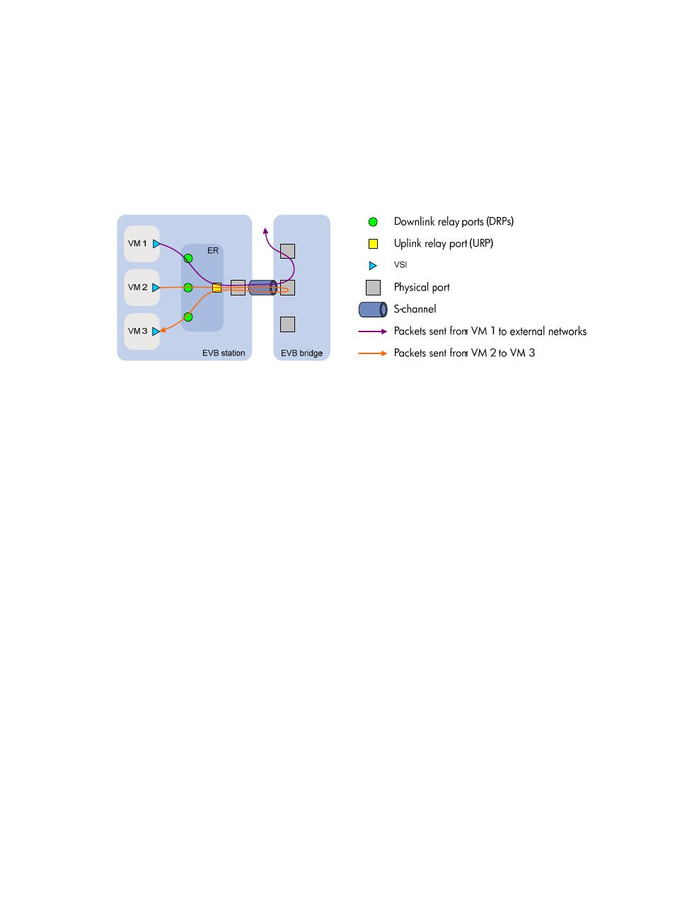
Basic concepts
shows the components on the EVB station and EVB bridge.
Figure 2 EVB architecture
•
Edge Relay—An ER transfers packets between one URP and one or more DRPs. An ER has one or
more DRPs and one URP. Both URP and DRPs are called ER ports. An EVB station can have multiple
ERs.
•
S-channel—A point-to-point S-VLAN established between a Port-mapping S-VLAN component in
an EVB station and a Port-mapping S-VLAN component in an EVB bridge. An S-channel
corresponds to the URP of an ER. On an EVB bridge, the end point of an S-channel is known as an
S-channel interface. An S-channel is identified by the S-VLAN Identifier (SVID) and the S-channel
Identifier (SCID), and the two values together are called an (SCID, SVID) pair.
•
Virtual Station Interface—A VSI is a port on a VM that directly connects to the DRP of an ER. A VSI
is associated with a logical entity called VSI instance, which is identified by the VSI Instance
Identifier (VSIID). A VSI is associated with a virtual interface called VSI interface on the EVB bridge
port to implement VM traffic management and policy configuration. A VSI interface can be
considered as a subinterface of an S-channel.
•
Reflective Relay—A RR is an operation mode in which a received frame on a port that supports this
function can be forwarded out of the same port. The EVB bridge uses this mode to forward traffic
among VMs on an EVB station, as shown in
EVB working mechanism
An EVB station and an EVB bridge go through the following steps to implement VM traffic management:
1.
Use the S-channel Discovery and Configuration Protocol (CDCP) to establish an S-channel.
CDCP is used to configure S-channels between stations and bridges. When a station creates or
deletes an S-channel, CDCP sends a CDCP TLV in an LLDP packet that is addressed using the
Nearest non-TPMR Bridge address to the bridge. The bridge creates or deletes the S-channel.
2.
Exchange EVB TLVs through LLDP to negotiate EVB capabilities for the S-channel, such as RR, ECP
parameters, and VDP parameters.
3.
Use the VSI Discovery and Configuration Protocol (VDP) to associate the VSIs of VMs with the
bridge port.